Hardware Interaction 1: MAS
Introduction
In this tutorial we introduce the Memory Access Service (MAS) and show how it is used within FSDK to access hardware.
To demonstrate this you will develop a Component Type to run on a Raspberry Pi 2 & 3 which communicates with an attached light sensor using MAS.
|
While this tutorial produces a Component Type for running on a Raspberry Pi 2 & 3 the ideas and techniques introduced are useful for developing Component Types which interact with subsystems on any of the platforms which the Flight Software Development Kit supports. |
For simplicity, whenever we reference the Raspberry Pi in this tutorial, we will refer to it as Pi.
|
In this tutorial, you will:
|
Before You Begin
In each terminal you use during this tutorial, the GEN1_ROOT environment
variable must be set. To do this, you must follow the
instructions.
You must run the commands found in this tutorial from within the OBSW/Source directory.
You can switch to this directory using the following command:
$ cd $GEN1_ROOT/OBSW/Source|
If this command fails, check that |
If you haven’t already, follow the steps in our Raspberry Pi How-to Guide to set up your Pi and install the correct toolchain in order to complete this tutorial.
Memory Access Service (MAS)
In space systems it is common for different functionality to be divided between independent subsystems. Typically these subsystems will be connected to onboard computers (OBCs) which monitor and control them.
A common interconnection pattern used to monitor and control subsystems is a "request-response" or "controller-peripheral" pattern.
In this interaction pattern:
-
The controller (OBC) initiates an interaction by issuing a request to the peripheral (the subsystem).
-
The request is either to write data to the subsystem (for instance, a command or register value) or read data from the subsystem (for example, some telemetry values).
-
The peripheral never sends unprompted data to the controller. It is only permitted to send data in response to requests received from the controller.
MAS is a Service which supports this interaction pattern, and specifically contains Service operations for:
-
Writing data to a peripheral.
-
Reading data from a peripheral.
-
Sequentially or simultaneously writing and reading data to and from a peripheral.
Typically Component Types which represent the high-level capabilities of this kind of subsystem will consume MAS. Component Types supporting interactions with hardware which follow this pattern (like I2C or SPI drivers) will provide it.
|
In the earlier Using a Service tutorial, you learned how the File Store Service (FSS) is a contract which defines operations for writing to and reading from files in a POSIX-like filesystem. MAS defines operations for writing to and reading from hardware, rather than files, but can be thought of in very similar terms. |
Analysis and Design
This tutorial will guide you through implementing a new Component Type to interact with the Pi’s light sensor.
The Component Type will:
-
Use Actions and Parameters to represent the high-level functionality of the sensor,
-
consume MAS, and use it to make requests of the hardware.
-
Need to be connected to a MAS provider once deployed. This MAS provider will send hardware requests to the sensor.
Before creating this Component Type, we first need to define what kind of functionality the sensor has, what requests it supports, and how to make these requests. We will also need to determine which MAS provider to use to make these requests.
The Peripheral
First consider the peripheral itself.
In this tutorial, the aim is to interact with a specific light sensor (M5 DLight Unit) connected to the Pi. This is an integrated light sensor built around the BH1750FVI ambient light sensor IC.
The datasheet for this sensor is available online.
The datasheet includes a lot of information. Much of it concerns the physical and electrical properties of the sensor. These are not relevant to your task of interacting with it through software.
Of more interest to you are the details of its data interface, and how to use it to measure light levels.
The datasheet states that the sensor uses an I2C interface. I2C is a physical layer protocol which is a common choice for communicating with sensors like this one. Importantly, it closely matches the "request-response" pattern supported by MAS.
The datasheet gives further information on the interface which you’ll need to implement your Component Type:
-
In the Page 4 state diagram, we can see that one time or continuous measurement can be carried out
-
Page 5 provides a table of instructions which can be sent to the sensor
-
Page 7 gives step-by-step procedures for requesting a measurement and reading it back from the sensor
-
Page 10 gives more detail on the I2C interface, including the 2 addresses the sensor uses
Assuming a one time measurement is sufficient, use the datasheet to plan what steps your Component Implementation will need to carry out.
Show an example procedure for the Component Implementation
-
Write the "one time H-resolution mode" command through I2C to the sensor
-
Wait 180ms to allow the measurement to complete
-
Read the measurement from the sensor
The simplicity of this procedure means you will be able to give your Component Type a single read-only Parameter for storing the light level.
The Controller
The other piece of hardware you need to consider is the controller. In this case the controller is the Broadcom Serial Controller (BSC) onboard the Pi, which is designed for writing and reading data to and from an I2C bus.
As with the peripheral in the previous section, you can find out more about how this controller works by referring to its datasheet.
If you were starting from scratch, you would need to write a Component Type which provided MAS. It would need to provide MAS operations by manipulating the BSC such that a MAS write would trigger an I2C write, for example.
To save time here you will use our I2CMaster Component Type provided in
the framework library. This Component Type provides MAS in
exactly the way you require.
The Connected System
The following sketch shows how our Component Types connect with the hardware on the board to enable interaction with the BH1750FVI subsystem.
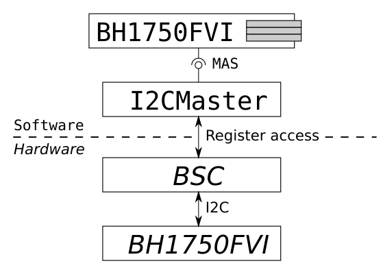
Notice that the I2CMaster Component Type provides MAS to represent the functionality of the BSC.
In a similar way, notice how the BH1750FVI Component Type represents the
capabilities of the BH1750FVI sensor with Actions and Parameters.
In constructing the system like this, and using MAS between the Component Types,
they are decoupled. Importantly, the BH1750FVI Component Type you are about
to implement can be instantiated on any platform with a Component Type which
provides MAS and uses it to give access to an I2C bus.
Now that we have identified the hardware in the system, you can move on to implementing the new BH1750FVI Component Type.
The BH1750FVI Component Type
To request data from the Pi’s light sensor, you will need to create a new Component Type.
As you have learned from previous tutorials, the first step in producing a new Component Type is to define its interfaces and characteristics in the
componentType.xml model.
|
When developing new Component Types it is often best to think carefully about how to define them before thinking too hard about how to implement them. This approach ensures the Component Type you produce will meet your needs and fit into the system. While some iteration between definition and implementation is usually needed, more time spent at the definition stage tends to reduce the time spent at the implementation stage. |
We have suggested you name it BH1750FVI after the specific device it supports. Naming it LightSensor might be easier on the eye, but it would be unclear exactly which light sensor it can communicate with.
Definition
Open a terminal in the fsdk-22.2/OBSW/Source/demo_pi directory and create a new component library using the following command:
codegen library new componentsThe above command generates the following directory structure within the demo_pi directory for the new library:
components
├── config
|   └── project.mk
├── inc
├── src
├── test
|   └── src
|       └── common
|           └── deployment
|               └── Deployment.c
└── Makefile
This library can now be used to hold new Component Types.
As the BH1750FVI Component requires MAS, we need to add a dependency to the component library that defines the MAS Component Type.
The project.mk file controls how the component library is built. Update the component library's project.mk file to include the framework directory.
# Dependencies (library directories)
DEPEND_DIRS = $(OBSW_ROOT)/framework|
We use |
While we are here we should also increase our DUTIL_LOG_LEVEL to 3 to enable more verbose logging.
Update the component library's DUTIL_LOG_LEVEL to 3.
# Preprocessor flags
CPPFLAGS += -DUTIL_LOG_LEVEL=3
Create the Component Type using the following command:
codegen componenttype new components --name BH1750FVIThis creates a componentType.xml for your new Component Type in the components/inc/BH1750FVI directory.
Open the BH1750FVI componentType.xml model.
Update the description and documentation elements to give more detail about what the Component Type does:
<Description>
  This component provides an interface to the BH1750FVI digital ambient light sensor.
</Description>
<Documentation><Markdown>
  Datasheet available from:

  https://m5stack.oss-cn-shenzhen.aliyuncs.com/resource/docs/datasheet/hat/BH1750FVI.pdf

  This component supports one time H-Resolution mode.
</Markdown></Documentation>|
Most of the elements in They make sharing Component Types between developers much easier, and give developers a way to communicate important implementation details to systems engineers and spacecraft operators. Remember that comparatively few end-users of your Component Types will have access to the C code you write. |
You will use MAS to issue commands to the light sensor. To do this, you will need to declare that BH1750FVI requires MAS.
Add the <Services> element just below the <!-- Services (Provided, Required)--> comment:
<Services>
  <Required><Service name="bus" type="io.MAS">
    <Description>
      Provides access to the I2C bus connected to the sensor.
    </Description>
  </Service></Required>
</Services>
As you learned in the earlier Using a Service
tutorial, adding this Service requirement makes BH1750FVI a MAS
consumer, which, when instantiated, must be connected to a MAS provider.
The BH1750FVI implementation can safely assume this MAS requirement will be
fulfilled.
Finally, your Component Type needs to expose the functionality it has to end users. We decided above that the only required functionality is to request one time light-level readings. This fits well with implementing a single Read-Only Parameter.
Add a <Parameters> element just below the <!-- Parameters --> comment and define a light Parameter which will return the current light reading:
<Parameters>
  <Parameter name="light" readOnly="true">
    <Description>
      The current ambient light reading, in lux.
    </Description>
    <Value type="unsigned" bits="16"/>
  </Parameter>
</Parameters>
The type for the Parameter is set to a 16-bit unsigned integer because the sensor returns 16-bit values. These values are then scaled down by a calibration factor to give a reading in lux.
Generate the BH1750FVI Component Type using the following command:
codegen componenttype generate components --name BH1750FVIImplementation
Having generated the Component Type, codegen has produced the BH1750FVI.c implementation file. You will need to modify this file to add the implementation.
Open components/src/BH1750FVI/BH1750FVI.c.
This Component Type's implementation is relatively simple. The majority of your effort will go into writing the BH1750FVI_getLight() Parameter getter function.
The procuedure for implementing this function was outlined above:
-
Write the "one time H-resolution mode" command through I2C to the sensor
-
Wait 180ms to allow the measurement to complete
-
Read the measurement from the sensor
As shown in the table on page 5 of the BH1750FVI datasheet, the "one time H-resolution mode" command code is a single byte: 0010 0000 in binary or 0x20 in hexadecimal.
In addition to this command code, notice that the examples on page 7 of the
datasheet show a variety of other fields that need to be set in the I2C
transaction. One of the benefits of using MAS is that these fields are all the
responsibility of the MAS provider. The BH1750FVI Component Type, as
the consumer, only needs to provide the data to write.
To request level-level readings from the sensor, the BH1750FVI_getLight() getter function needs to call the BH1750FVI_MAS_write() function, which is used to send the "one time H-resolution mode" command code (0x20) to the sensor.
You can find the BH1750FVI_MAS_write() function declaration in the BH1750FVI_MAS_package.h header file.
Refer to the following implementation and update the BH1750FVI_getLight() getter function.
Show the MAS write added to BH1750FVI_getLight() getter function.
status_t BH1750FVI_getLight
(
BH1750FVI_t *pt_BH1750FVI,
ui16_t *pu16_Value
)
{
status_t t_Status; /* The current status */
TASK_PROTECTED_START(&pt_BH1750FVI->t_Lock, >_LockTimeout, t_Status)
{
- /* TODO: Implement light get accessor */
- t_Status = STATUS_NOT_IMPLEMENTED;
+ ui8_t u8_WriteData;
+
+ /* Send the "one time H-resolution mode" command */
+ u8_WriteData = 0x20;
+
+ /* Write the data to the device */
+ t_Status = BH1750FVI_MAS_writeBus(
+ pt_BH1750FVI,
+ >_LockTimeout,
+ 0,
+ 0,
+ NULL,
+ &u8_WriteData,
+ 1);
}
TASK_PROTECTED_END(&pt_BH1750FVI->t_Lock, >_LockTimeout, t_Status);
return t_Status;
}We need to wait 180ms while the sensor is recording light-levels.
In the BH1750FVI_getLight() getter function, add a call to the Task_Time_delayShortTime() function to wait for 180ms.
Show the delay added to BH1750FVI_getLight() getter function.
status_t BH1750FVI_getLight
(
BH1750FVI_t *pt_BH1750FVI,
ui16_t *pu16_Value
)
{
status_t t_Status; /* The current status */
TASK_PROTECTED_START(&pt_BH1750FVI->t_Lock, >_LockTimeout, t_Status)
{
ui8_t u8_WriteData;
/* Send the "one time H-resolution mode" command */
u8_WriteData = 0x20;
/* Write the data to the device */
t_Status = BH1750FVI_MAS_writeBus(
pt_BH1750FVI,
>_LockTimeout,
0,
0,
NULL,
&u8_WriteData,
1);
+ if (t_Status == STATUS_SUCCESS)
+ {
+ /* Wait 180ms time for the measurement to be taken */
+ t_Status = Task_Time_delayShortTime(180uL * 1000);
+ }
}
TASK_PROTECTED_END(&pt_BH1750FVI->t_Lock, >_LockTimeout, t_Status);
return t_Status;
}After waiting for the appropriate length of time, the final step is to read the measured result and convert it to lux. To receive the raw measurement, you need to request a 2-byte MAS read.
The BH1750FVI_MAS_read() can be used to receive light-levels from the sensor.
In BH1750FVI_getLight() getter function, add a call to BH1750FVI_MAS_read() function to read the 2-byte measurement from the sensor and record the value in the .
The 2-byte value will then be stored in the ru8_ReadData array.
Show the MAS read added to BH1750FVI_getLight() getter function.
status_t BH1750FVI_getLight
(
BH1750FVI_t *pt_BH1750FVI,
ui16_t *pu16_Value
)
{
status_t t_Status; /* The current status */
TASK_PROTECTED_START(&pt_BH1750FVI->t_Lock, >_LockTimeout, t_Status)
{
ui8_t u8_WriteData;
/* Send the "one time H-resolution mode" command */
u8_WriteData = 0x20;
/* Write the data to the device */
t_Status = BH1750FVI_MAS_writeBus(
pt_BH1750FVI,
>_LockTimeout,
0,
0,
NULL,
&u8_WriteData,
1);
if (t_Status == STATUS_SUCCESS)
{
/* Wait 180ms time for the measurement to be taken */
t_Status = Task_Time_delayShortTime(180uL * 1000);
}
+
+ if (t_Status == STATUS_SUCCESS)
+ {
+ /* A buffer to read into, and its length. */
+ ui8_t ru8_ReadData[2];
+ ui32_t u32_ReadDataLength = sizeof(ru8_ReadData);
+
+ /* Read the measurement from the device */
+ t_Status = BH1750FVI_MAS_readBus(
+ pt_BH1750FVI,
+ >_LockTimeout,
+ 0,
+ 0,
+ NULL,
+ &ru8_ReadData[0],
+ &u32_ReadDataLength);
+ }
}
TASK_PROTECTED_END(&pt_BH1750FVI->t_Lock, >_LockTimeout, t_Status);
return t_Status;
}The raw value can now be converted into lux. The examples on page 7 of the BH1750FVI datasheet use a nominal conversion factor of 1.2.
The raw measurement is stored in the ru8_ReadData array. To get the light level in lux, convert this array to an unsigned 16-bit integer (uint16_t).
We can use the Util_Endian_u16FromNetwork utility function to perform this conversion.
Show the value conversion code added to BH1750FVI_getLight() getter function.
if (t_Status == STATUS_SUCCESS)
{
/* A buffer to read into, and its length. */
ui8_t ru8_ReadData[2];
ui32_t u32_ReadDataLength = sizeof(ru8_ReadData);
/* Read the measurement from the device */
t_Status = BH1750FVI_MAS_readBus(
pt_BH1750FVI,
>_LockTimeout,
0,
0,
NULL,
&ru8_ReadData[0],
&u32_ReadDataLength);
+ if (t_Status == STATUS_SUCCESS)
+ {
+ ui16_t u16_RawValue;
+ float32_t f32_LuxValue;
+
+ Util_Endian_u16FromNetwork(&ru8_ReadData[0], &u16_RawValue);
+
+ /* Convert the sample to lux by dividing by 1.2 */
+ f32_LuxValue = (float32_t)u16_RawValue / 1.2f;
+
+ *pu16_Value = (ui16_t)f32_LuxValue;
+ }
}
}
TASK_PROTECTED_END(&pt_BH1750FVI->t_Lock, >_LockTimeout, t_Status);
return t_Status;
}|
The |
For the provided implementation to work, you also need to include the header file for the endian functions used.
At the top of the BH1750FVI.c implementation file, include the following header file:
#include "util/Util_Endian.h"|
It is good practice to now address the remaining |
Open the BH1750FVI.h header file and update the TODO comment in the BH1750FVI_Init_t structure to inform users that no Initialisation Data is required.
As the Component Type implementation doesn’t requite additional states, remove the TODO comment in the BH1750FVI_t component type structure.
The demo_pi Deployment
Before using the BH1750FVI Component Type to interact with the light sensor, you must instantiate it in our demo_pi Deployment Type.
|
You’ll now update the provided |
New component instances
Open the demo_pi deployment.xml model which can be found in the demo_pi directory.
The demo_pi Deployment contains a number of component instances which are not in use. We can safley remove these and include the new BH1750FVI and I2CMaster Component Types.
Remove the ArduCAM and GPIO component instances from the deployment.xml model and add the BH1750FVI and I2CMaster component instances.
Show the component instances added to the deployment.xml file.
<?xml version="1.0" encoding="UTF-8"?>
<!--
    This file describes the demo_pi deployment.
-->
<ModelElement xmlns="http://www.brightascension.com/schemas/gen1/model"
  xmlns:xsi="http://www.w3.org/2001/XMLSchema-instance">
  <Deployment name="demo_pi">
    <Description>
      This is an example deployment of GenerationOne for the Raspberry PI.
    </Description>
    <!-- Component type imports -->
    <Import>
      <!-- The component types used by this deployment -->
      <Use type="Version" />
      <Use type="storage.Storage" />
      <Use type="ConfigManager" />
      <Use type="io.driver.OSTime" />
      <Use type="storage.config.FileConfigStore" />
      <Use type="storage.fs.PosixFS" />
      <Use type="storage.FileStorageProvider" />
      <Use type="storage.FileSystemManager" />
      <Use type="event.EventDispatcher" />
      <Use type="io.net.tcp.TCPServer" />
      <Use type="io.net.PacketStream" />
      <Use type="io.net.SpacePacket" />
      <Use type="io.net.pus.PUSCore" />
      <Use type="io.net.pus.PUSHK" />
      <Use type="io.net.pus.PUSEvent" />
      <Use type="io.net.pus.PUSLDT" />
      <Use type="io.net.pus.PUSAMS" />
      <Use type="io.net.CFDP" />
      <Use type="tmtc.TMBeacon" />
      <Use type="tmtc.TMDebug" />
      <Use type="tmtc.TMTCEvent" />
      <Use type="io.net.ParamTransfer" />
      <Use type="component.AAS.AASTarget" />
      <Use type="component.PAS.PASTarget" />
      <Use type="subsys.OBT" />
      <Use type="Dummy" />
      <Use type="logging.CommandLogger" />
      <Use type="logging.EventLogger" />
      <Use type="DataPool" />
      <Use type="Sampler" />
      <Use type="Aggregator" />
      <Use type="Monitor" />
      <Use type="logging.DataLogger" />
      <Use type="auto.EventAction" />
      <Use type="auto.TimeAction" />
      <Use type="io.bus.spi.SPIMaster" />
      <Use type="io.bus.i2c.I2CMaster" />
-      <Use type="subsys.ArduCAM" />
-      <Use type="io.driver.GPIO" />
+      <Use type="BH1750FVI" />
    </Import>
    <!-- Component deployment -->
    <Deploy>
      <!-- Component Groups -->
      <ComponentGroup name="cdh">
        <Description>
          Command and data handling group.
        </Description>
        <Documentation>
          <Text>
            Contains the components used to assist with the function of the
            spacecraft such as loggers, autonomous components and TMTC components.
          </Text>
        </Documentation>
      </ComponentGroup>
      <ComponentGroup name="cdh.logging">
        <Description>
          Group containing the logging components.
        </Description>
        <Documentation>
          <Markdown>
            For demo_linux, the included logging components are:
            - BaseLogger (used for logging data)
            - EventLogger (used to log raised events)
            - TCLogger (used for logging Telecommands)
          </Markdown>
        </Documentation>
      </ComponentGroup>
      <ComponentGroup name="cdh.tmtc">
        <Description>
          Group containing the components that handle TMTC.
        </Description>
        <Documentation>
          <Text>
            TMTC Components are used to connect the comms stack to the components
            so that action/parameter/event interactions can occur.
          </Text>
        </Documentation>
      </ComponentGroup>
      <ComponentGroup name="comms">
        <Description>
          The communications stack group.
        </Description>
        <Documentation>
          <Markdown>
            Contains the components used to form the comms stack.
            For demo_linux, this includes:
            - TCP Client
            - PacketStream
            - SpacePacket
            - PUS components
          </Markdown>
        </Documentation>
      </ComponentGroup>
      <ComponentGroup name="comms.pus">
        <Description>
          Group containing the PUS components.
        </Description>
        <Documentation>
          <Text>
            PUS components are used to provide functionality that corresponds to
            the PUS standard. See ECSS-E-70-41A.
          </Text>
        </Documentation>
      </ComponentGroup>
      <ComponentGroup name="comms.services">
        <Description>
          Group containing the service proxy components.
        </Description>
        <Documentation>
          <Text>
            Service proxies allow services to be provided to external systems and
            allow this deployment to access services provided externally.
          </Text>
        </Documentation>
      </ComponentGroup>
      <ComponentGroup name="core">
        <Description>
          Group containing the core components for the deployment.
        </Description>
        <Documentation>
          <Text>
            Contains components integral to the functionality of the OBSW.
          </Text>
        </Documentation>
      </ComponentGroup>
      <ComponentGroup name="platform">
        <Description>
          Group containing the components integral to the platform being deployed.
        </Description>
        <Documentation>
          <Text>
            For demo_linx, no platform specific hardware or software is required,
            however DummySubsys can be used to simulate TMTC with a component.
          </Text>
        </Documentation>
      </ComponentGroup>
      <!-- Component Instances -->
      <Component name="Version" type="Version" />
      <Component name="core.Storage" type="storage.Storage" />
      <Component name="core.ConfigurationManager" type="ConfigManager" />
      <Component name="core.Time" type="io.driver.OSTime" />
      <Component name="core.OBT" type="subsys.OBT">
        <Connections>
          <Services>
            <Service name="time" component="core.Time" service="time" />
          </Services>
        </Connections>
      </Component>
      <Component name="core.FileSystem" type="storage.fs.PosixFS" />
      <Component name="core.FileConfigStore" type="storage.config.FileConfigStore">
        <Connections>
          <Services>
            <Service name="fs" component="core.FileSystem" service="fs" />
          </Services>
        </Connections>
      </Component>
      <Component name="core.FileStorageProvider" type="storage.FileStorageProvider">
        <Connections>
          <Services>
            <Service name="fs" component="core.FileSystem" service="fs" />
          </Services>
        </Connections>
      </Component>
      <Component name="core.FileSystemManager" type="storage.FileSystemManager">
        <Connections>
          <Services>
            <Service name="fs" component="core.FileSystem" service="fs" />
          </Services>
        </Connections>
        <Tasks>
          <SporadicTask name="decompress" priority="3" />
        </Tasks>
      </Component>
      <Component name="core.EventDispatcher" type="event.EventDispatcher">
        <Tasks>
          <PeriodicTask name="dispatcher" period="1.0" priority="2" />
        </Tasks>
      </Component>
      <Component name="comms.TCPServer" type="io.net.tcp.TCPServer">
        <Tasks>
          <PeriodicTask name="receive" priority="3" />
          <SporadicTask name="receiveTimeout" priority="3" />
        </Tasks>
      </Component>
      <Component name="comms.PacketStream" type="io.net.PacketStream">
        <Connections>
          <Services>
            <Service name="stream" component="comms.TCPServer" service="data" />
          </Services>
        </Connections>
        <Tasks>
          <SporadicTask name="receive" priority="3" />
          <SporadicTask name="receiveTimeout" priority="3" />
        </Tasks>
      </Component>
      <Component name="comms.SpacePacket" type="io.net.SpacePacket">
        <Connections>
          <Services>
            <Service name="spacePacket" component="comms.PacketStream" service="packet" />
          </Services>
        </Connections>
        <Tasks>
          <SporadicTask name="transmit" priority="3" />
          <SporadicTask name="transmitTimeout" priority="3" />
          <SporadicTask name="receive" priority="3" />
          <SporadicTask name="receiveTimeout" priority="3" />
        </Tasks>
      </Component>
      <Component name="comms.pus.PUSCore" type="io.net.pus.PUSCore">
        <Connections>
          <Services>
            <Service name="pusPacket" component="comms.SpacePacket" service="dataPacket" channel="0" />
          </Services>
        </Connections>
        <Tasks>
          <SporadicTask name="transmit" priority="3" />
          <SporadicTask name="transmitTimeout" priority="3" />
          <SporadicTask name="receive" priority="3" />
          <SporadicTask name="receiveTimeout" priority="3" />
        </Tasks>
      </Component>
      <Component name="comms.pus.PUSHK" type="io.net.pus.PUSHK">
        <Connections>
          <Services>
            <Service name="pusSend" component="comms.pus.PUSCore" service="dataPacket" channel="0" />
            <Service name="pusReceive" component="comms.pus.PUSCore" service="dataPacket"
              channel="0" />
          </Services>
        </Connections>
        <Tasks>
          <SporadicTask name="transmit" priority="3" />
          <SporadicTask name="receive" priority="3" />
        </Tasks>
      </Component>
      <Component name="comms.pus.PUSEvent" type="io.net.pus.PUSEvent">
        <Connections>
          <Services>
            <Service name="pusSend" component="comms.pus.PUSCore" service="dataPacket" channel="1" />
            <Service name="pusReceive" component="comms.pus.PUSCore" service="dataPacket"
              channel="1" />
          </Services>
        </Connections>
        <Tasks>
          <SporadicTask name="transmit" priority="3" />
          <SporadicTask name="receive" priority="3" />
        </Tasks>
      </Component>
      <Component name="comms.pus.PUSLDT" type="io.net.pus.PUSLDT">
        <Connections>
          <Services>
            <Service name="pusPacket" component="comms.pus.PUSCore" service="dataPacket" channel="2" />
          </Services>
        </Connections>
        <Tasks>
          <SporadicTask name="transmit" priority="3" />
          <SporadicTask name="transmitTimeout" priority="3" />
          <SporadicTask name="transmitTransferTimeout" priority="3" />
          <SporadicTask name="receive" priority="3" />
          <SporadicTask name="receiveTimeout" priority="3" />
          <SporadicTask name="receiveTransferTimeout" priority="3" />
        </Tasks>
      </Component>
      <Component name="comms.pus.PUSToAAS" type="io.net.pus.PUSAMS">
        <Connections>
          <Services>
            <Service name="pusSend" component="comms.pus.PUSCore" service="dataPacket" channel="4" />
            <Service name="pusReceive" component="comms.pus.PUSCore" service="dataPacket"
              channel="4" />
            <Service name="target" component="comms.services.AASTarget" service="remote" />
          </Services>
        </Connections>
        <Tasks>
          <SporadicTask name="transmit" priority="3" />
          <SporadicTask name="receive" priority="3" />
          <SporadicTask name="requestCompleteTarget" priority="3" />
        </Tasks>
      </Component>
      <Component name="comms.CFDP" type="io.net.CFDP">
        <Connections>
          <Services>
            <Service name="fs" component="core.FileSystem" service="fs" />
            <Service name="ut" component="comms.SpacePacket" service="dataPacket" channel="1" />
          </Services>
        </Connections>
        <Tasks>
          <SporadicTask name="transmit" priority="3" />
          <SporadicTask name="receive" priority="3" />
          <SporadicTask name="timer" priority="3" />
          <SporadicTask name="remoteRequestComplete" priority="3" />
        </Tasks>
      </Component>
      <Component name="comms.services.AASTarget" type="component.AAS.AASTarget" />
      <Component name="comms.pus.PUSToPAS" type="io.net.pus.PUSAMS">
        <Connections>
          <Services>
            <Service name="pusSend" component="comms.pus.PUSCore" service="dataPacket" channel="5" />
            <Service name="pusReceive" component="comms.pus.PUSCore" service="dataPacket"
              channel="5" />
            <Service name="target" component="comms.services.PASTarget" service="remote" />
          </Services>
        </Connections>
        <Tasks>
          <SporadicTask name="transmit" priority="3" />
          <SporadicTask name="receive" priority="3" />
          <SporadicTask name="requestCompleteTarget" priority="3" />
        </Tasks>
      </Component>
      <Component name="comms.services.PASTarget" type="component.PAS.PASTarget" />
      <Component name="comms.pus.PUSToParamTransfer" type="io.net.pus.PUSAMS">
        <Connections>
          <Services>
            <Service name="pusSend" component="comms.pus.PUSCore" service="dataPacket" channel="6" />
            <Service name="pusReceive" component="comms.pus.PUSCore" service="dataPacket"
              channel="6" />
            <Service name="target" component="comms.ParamTransfer" service="remote" />
          </Services>
        </Connections>
        <Tasks>
          <SporadicTask name="transmit" priority="3" />
          <SporadicTask name="receive" priority="3" />
          <SporadicTask name="requestCompleteTarget" priority="3" />
        </Tasks>
      </Component>
      <Component name="comms.ParamTransfer" type="io.net.ParamTransfer">
        <Connections>
          <Services>
            <Service name="ldt" component="comms.pus.PUSLDT" service="dataPacket" />
          </Services>
        </Connections>
        <Tasks>
          <SporadicTask name="transmit" priority="3" />
          <SporadicTask name="receive" priority="3" />
        </Tasks>
      </Component>
      <Component name="cdh.tmtc.TMBeacon" type="tmtc.TMBeacon">
        <Connections>
          <Services>
            <Service name="hkHandler" component="comms.pus.PUSHK" service="hkReporting" />
          </Services>
        </Connections>
        <Tasks>
          <PeriodicTask name="send" period="5.0" priority="2" />
        </Tasks>
      </Component>
      <Component name="cdh.tmtc.TMDebug" type="tmtc.TMDebug">
        <Connections>
          <Services>
            <Service name="pusSend" component="comms.pus.PUSCore" service="dataPacket" channel="3" />
          </Services>
        </Connections>
        <Tasks>
          <SporadicTask name="transmit" priority="3" />
        </Tasks>
      </Component>
      <Component name="cdh.tmtc.TMTCEvent" type="tmtc.TMTCEvent">
        <Connections>
          <Components>
            <Component name="eventHandler" component="comms.pus.PUSEvent" />
          </Components>
        </Connections>
      </Component>
      <Component name="cdh.logging.TCLogger" type="logging.CommandLogger">
        <Connections>
          <Services>
            <Service name="timestamp" component="core.Time" service="time" />
          </Services>
        </Connections>
        <Tasks>
          <PeriodicTask name="store" period="10.0" priority="2" />
        </Tasks>
      </Component>
      <Component name="platform.DummySubsys1" type="Dummy" />
      <Component name="platform.PlatformSPI" type="io.bus.spi.SPIMaster">
        <Description>
          The main SPI bus for interfacing to the test SPI
        </Description>
      </Component>
-      <Component name="platform.PlatformI2C" type="io.bus.i2c.I2CMaster">
-        <Description>
-          Platform I2C bus
-        </Description>
-      </Component>
-      <Component name="platform.ArduCAM" type="subsys.ArduCAM">
-        <Connections>
-          <Services>
-            <Service name="arduChip" component="platform.PlatformSPI" service="data" channel="0" />
-            <Service name="sensor" component="platform.PlatformI2C" service="data" channel="0" />
-            <Service name="fs" component="core.FileSystem" service="fs" />
-          </Services>
-        </Connections>
-        <Tasks>
-          <SporadicTask name="capture" priority="3" />
-        </Tasks>
-      </Component>
-      <Component name="platform.GPIO" type="io.driver.GPIO" />
+      <Component name="BSC" type="io.bus.i2c.I2CMaster">
+        <Description>
+          The Broadcomm Serial Controller which controls the platform I2C bus.
+        </Description>
+      </Component>
+      <Component name="M5DLightUnit" type="BH1750FVI">
+        <Description>
+          Provides access to the M5 DLight Unit sensor connected via I2C.
+        </Description>
+        <Connections>
+          <Services>
+            <Service name="bus" component="BSC" service="data" channel="0" />
+          </Services>
+        </Connections>
+      </Component>
      <Component name="cdh.logging.EventLogger" type="logging.EventLogger">
        <Connections>
          <Services>
            <Service name="timestamp" component="core.Time" service="time" />
          </Services>
        </Connections>
        <Tasks>
          <PeriodicTask name="store" period="10.0" priority="2" />
        </Tasks>
      </Component>
      <Component name="cdh.DataPool" type="DataPool">
        <Connections>
          <Services>
            <Service name="time" component="core.Time" service="time" />
          </Services>
        </Connections>
        <ParameterAliases>
          <ParameterBlock blockName="poolParameters">
            <ComponentParameter name="DummySubsys1" component="platform.DummySubsys1"
              parameter="dummyParam8" />
            <ComponentParameter name="DummySubsys1" component="platform.DummySubsys1"
              parameter="dummyParam16" />
            <ComponentParameter name="DummySubsys1" component="platform.DummySubsys1"
              parameter="dummyParam32" />
          </ParameterBlock>
        </ParameterAliases>
      </Component>
      <Component name="cdh.BeaconAggregator" type="Aggregator" />
      <Component name="cdh.BaseSampler" type="Sampler">
        <Connections>
          <Components>
            <Component name="DataPool" component="cdh.DataPool" />
          </Components>
        </Connections>
        <Tasks>
          <PeriodicTask name="sample" period="5.0" priority="2" />
        </Tasks>
      </Component>
      <Component name="cdh.BaseAggregator" type="Aggregator" />
      <Component name="cdh.BaseMonitor" type="Monitor">
        <Tasks>
          <PeriodicTask name="refresh" period="5.0" priority="2" />
        </Tasks>
      </Component>
      <Component name="cdh.logging.BaseLogger" type="logging.DataLogger">
        <Connections>
          <Services>
            <Service name="timestamp" component="core.Time" service="time" />
          </Services>
        </Connections>
        <Tasks>
          <PeriodicTask name="sample" period="10.0" priority="2" />
          <PeriodicTask name="store" period="60.0" priority="2" />
        </Tasks>
      </Component>
      <Component name="cdh.EventAction" type="auto.EventAction" />
      <Component name="cdh.TimeAction" type="auto.TimeAction">
        <Connections>
          <Services>
            <Service name="time" component="core.Time" service="time" />
          </Services>
        </Connections>
        <Tasks>
          <PeriodicTask name="main" period="1.0" priority="2" />
        </Tasks>
      </Component>
    </Deploy>
  </Deployment>
</ModelElement>
BSC is an instance of the io.bus.i2c.I2CMaster Component Type used to communicate with the Pi’s Broadcom Serial Control. It is an MAS provider and is the controller on the I2C bus.
M5DLightUnit is an instance of your new BH1750FVI Component Type. It is a
MAS consumer which issues MAS operations to control the peripheral -
the M5 DLight Unit.
As you would expect, this addition to the Deployment Type matches the design we discussed above, but in XML instead of as a block diagram.
Notice how the io.MAS requirement which you previously gave your BH1750FVI Component Type has been satisfied in the connections section of the M5DLightUnit component instance. The <Service> element can be read as follows: "the Service requirement named bus has been fulfilled by the BSC component instance's data Service provision".
Notice also that we have specified channel="0". The I2CMaster
Component Type provides multiple channels of io.MAS. This
lets it fulfil the Service requirements of multiple consumers. It offers
multiple channels by accessing a different I2C address on each channel. You
only require access to a single I2C peripheral, so below you’ll set up your
BSC component instance to only provide a single channel - channel 0.
Now that you have updated the Deployment Type, you can generate the SCDB in which it is instantiated. This will verify that you have connected the various component instances in the Deployment Type correctly.
Update Deployment's project.mk to include the component library we created earlier.
# Dependencies (library directories)
DEPEND_DIRS = $(OBSW_ROOT)/app $(OBSW_ROOT)/framework ../components
Generate the demo_pi Deployment Type using the following command:
codegen deployment generate demo_pi/ --build-config pi3This produces a SCDB which will allow you to interact with the Deployment Instance via tmtclab. It also produces empty Initialisation Data for the new component instances which you will populate later.
Setting the Initialisation Data
The final step before building the demo_pi Mission is to
populate the Initialisation Data for the two new component instances.
Open demo_pi/src/init/BSC_Init.c.
Here you must specify the Initialisation Data for the BSC component instance using the definition of the I2CController_Init_t structure defined in the I2CController.h header file.
You will need to use values in this structure as follows:
-
u8_BusIndexneeds to be set to1as the light sensor is connected to bus 1 of the Pi’s I2C. -
pt_Channelsneeds to be a valid pointer to an array ofI2CController_Channel_tstructures. -
u32_NumOfChannelsneeds to be set to the length of the arraypt_Channelspoints to. -
b_Enabledshould be set totrueso that the BSC peripheral is enabled at start up.
The number of Service channels which BSC provides is determined by the
u32_NumOfChannels Initialisation Data member.
As discussed above, only one channel is required as you only require access to the single M5 DLight Unit on the I2C bus.
This means that the array pointed to by pt_Channels only needs to contain a single I2CController_Channel_t structure. That structure has only a single member,
u8_PeripheralAddress, which should be set to the peripheral address of the sensor. This is documented in the BH1750FVI datasheet as 0x23.
Set the Initialisation Data for the BSC component instance using the values given above.
Show the new Initialisation Data
+ /** The list of channels for BSC */
+ static const I2CMaster_Channel_t grt_Channels[] =
+   {
+       {
+           /* Unshifted slave address of the connected BH1750FVI */
+           .u8_SlaveAddress = 0x23
+       }
+   };

/**The BSC initialisation data */
const I2CMaster_Init_t gt_BSCInit =
    {
-       /* TODO: Add initialisation data for the BSC component */
+       /** The index of the I2C bus */
+       .u8_BusIndex = 1,
+       /** Channel list */
+       .pt_Channels = &grt_Channels[0],
+       /** Number of available channels */
+       .u32_NumOfChannels = ARRAY_COUNT(grt_Channels),
+       /** Whether the I2C should be enabled by default */
+       .b_Enabled = TRUE
    };
With the BSC component instance set up properly, the same must be done for the M5DLightUnit component instance.
Open demo_pi/src/init/M5DLightUnit_Init.c.
Recall that you updated the definition of BH1750FVI_Init_t in BH1750FVI.h with a comment indicating that no Initialisation Data is required. The
Initialisation Data in the M5DLightUnit instance should therefore be empty.
Update the comment in the BH1750FVI_Init_t Initialisation Data structure to state that no Initialisation Data is required.
With the Initialisation Data complete, you can now move on to testing your flight software on the target hardware.
Testing the Light Sensor
|
In order to build and run Flight Software Development Kit flight software on your Pi you will need to follow the steps in our Raspberry Pi How-to Guide! The steps below will fail if your machine or the Pi are not correctly configured. |
If you haven’t already, connect and power up the Pi.
Ensure that the light sensor is properly connected to I2C bus 1 of the Pi.
Build the demo_pi Deployment using the following command in the OBSW/Source directory:
make -C demo_pi/ force target CONFIG=pi3This builds a binary for the Deployment Instance that can now be run on the Pi. The binary is found here:
demo_pi/pi3/bin/demo_piTo run this binary on the Pi, you first need to copy it over to the device.
Copy the binary to the platform using the following command and entering your password when prompted.
If you’ve changed your username or hostname from the default values, be sure to use your own.
scp demo_pi/pi3/bin/demo_pi pi@raspberrypi:With the binary on the Pi’s filesystem, you can now log in to the Pi and execute it.
Using another terminal, connect to the Pi using the following SSH command:
ssh pi@raspberrypiOnce connected, you can run the binary like you would any other executable.
Using the same terminal, run the binary using the following command:
./demo_piIf successful, the following output should be printed to the terminal:
INF: Main.c:67 Platform initialisation successful
INF: Deployment.c:36 Deployment initialisation successful|
For more in depth instructions on how to run Deployment Instances on the Pi, refer to the remaining sections of the Raspberry Pi How-to Guide. |
Now that the Deployment Instance is running on the platform, you can connect to it using tmtclab and test out the new light sensor functionality.
Open tmtclab, load the SCDB, and connect to the Deployment Instance.
Once connected, use the Commanding view, locate the M5DLightUnit component instance and get the current value of the light Parameter.
Experiment with shining different levels of light on the sensor and requesting updated readings. Verify that the values returned are as expected.
Wrap Up
In this tutorial you have:
-
Learned how to interact with subsystems using the Memory Access Service (MAS).
-
Gained a deeper understanding of how Services are used in Flight Software Development Kit and how they can be used to connect component instances together.
-
Learned about how the Flight Software Development Kit development workflow can be used to produce Component Types which interact with hardware subsystems.
In the next tutorial, we’ll introduce a new Service for interacting with hardware in a "peer-to-peer" fashion, and you’ll create a Component Type which consumes this Service.