User Manual: GenerationOne FSDK
1. Introduction
This manual is intended as an introduction to the GenerationOne Flight Software Development Kit (FSDK). The GenerationOne FSDK is a software framework, library and tool set for the creation of spacecraft onboard software.
1.1. How this Manual is Structured
We have tried to structure this manual to allow it to be used as a reference whilst you are learning to use the FSDK. The first three chapters after the preamble introduce the general concepts and principles behind the GenerationOne FSDK and describe how to install and set up the software on your development workstation. As part of this introduction we describe an example, supplied with the software, which you can compile and use on your workstation immediately after installation.
In the following three chapters we present a practical guide to creating onboard software in the form of tutorials and a reference.
-
Section 6 (Working with a Deployment) describes how to create onboard software from existing software components included as part of the FSDK;
-
Section 7 (Working with a Component) provides a reference for the different parts of a component as well as how that integrates with a deployment;
-
Section 8 (Components tutorial) describes how to create a software component of your own and add it to a deployment.
Note that the tutorial material in Section 6, Section 7 and Section 8 is being replaced by new HTML tutorials. These may be found under Documentation/Tutorials.
The following (Section 9) presents a more detailed guide to TMTC Lab, the graphical software environment which can be used as the “ground” when developing and testing the onboard software.
Finally, the remaining chapters detail the support that the FSDK offers for different operating systems (such as POSIX and FreeRTOS) and different platforms (such as Linux, the Clyde Space OBC and the GOMspace Nanomind). An example is supplied for each supported platform, and the chapter on that platform describes the example.
1.2. How to Use this Manual
There is a wealth of material in this manual, and each reader will have different preferences around how to get the most value from it. For a new FSDK user, we recommend the following order:
-
If you plan on working within the FSDK virtual machine, set it up on your host machine as described in Section 4.1.
-
If you would rather work with the FSDK installed natively on your machine, carry out the FSDK setup steps in Section 3.
-
Proceed to the new HTML tutorials. These are not part of this document, but may be found in the FSDK directory under
Documentation/Tutorials. -
Section 2 will then revisit the topics of those tutorials in a more general setting. It will also introduce more features of the FSDK, and discuss some of the structural features of GenerationOne flight software.
-
Next, the latest iteration of the User Manual tutorials may be of interest. These are found in Section 6, Section 7 and Section 8 and cover more material, but in less detail, than the new HTML tutorials.
-
Finally, to apply your new knowledge to other platforms, refer to the relevant platform and operating specific chapters towards the end of this manual.
2. Overview
The Bright Ascension GenerationOne FSDK has been designed specifically to make the development, or modification, of onboard software faster and easier to validate. To achieve this we have based the software on components each of which has a regular interface. Components can be added and removed easily and help encapsulate the code which provides the key functions of the onboard software in a form which is amenable to intensive unit testing. The library of components supplied with the FSDK covers most of the typical functions that onboard software is required to perform; also included are a set of components to permit interfacing to common hardware.
This chapter gives an overview of the onboard software and the design principles we have followed. The information presented here should help you to understand the general layout of the supplied code base.
We start by presenting on overview of the software from the perspective of an operator using a spacecraft or system which is implemented using the onboard software. After that, we delve a little deeper, describing the concepts and principles behind the software from the point of a view of a developer using the software to implement custom onboard software for a spacecraft or system.
2.1. A User’s View of the Software
Conceptually, the software as seen by an operator consists of a loosely coupled set of components. A component is a re-usable stand-alone software module which encapsulates a related set of functions and data, and which has a well-defined interface.
Some of the components represent particular hardware subsystems, for example the EPS component provides a software interface to the Electrical Power System (EPS) hardware subsystem which is used to provide regulated electrical power to other hardware. Other components are entirely software based and provide capabilities such as telemetry aggregation or monitoring.
2.1.1. Interacting with Components
The interface to a component takes the form of actions and parameters. Unusual conditions arising when attempting to use an action or parameter give rise to exceptions; to indicate unusual conditions which occur asynchronously to these operations, components may also issue events.
2.1.1.1. Actions
An action is a function that the component can be commanded to perform. This is known as invoking the action. Some actions may accept a single parameter. For example the EPS has a cycleBus action which is used to power cycle one or more power buses. We would refer to this action using the notation
EPS.cycleBus()
While, in this document, we always refer to actions by a logical label, on board each action is actually identified by a numeric ID. The numeric ID for a particular action will depend on the exact build of the onboard software so it may be different across different uses of the FSDK. However, once a software image has been built, the numeric ID will not change.
2.1.1.2. Parameters
Parameters represent data associated with a component. A 'Get' operation is used to read the current value of a parameter, while a 'Set' operation is used to change it. Some parameters are read-only; these often represent some on-board measurement. For example, the parameter EPS.current3v3 represents the current through the 3.3V power bus as measured by the EPS subsystem. Other parameters are read-write and are used to modify the configuration of a component. For example by setting the value of the EPS.watchdogEnable parameter, the user can enable or disable periodic servicing of the EPS watchdog.
The parameters above are scalar, but it is also possible to have vector parameters which have a number of rows of equal length. For example, the subsys.CSLADM component has a parameter subsys.CSLADM.antennaStatus, with 4 rows, representing the status of each of the 4 antennae it controls.
While some parameters have a fixed number of rows, others have a variable number of rows. For example, the list of parameters to be aggregated by an aggregator component is a variable-length parameter. It’s possible to query a parameter to find out the current size of either it’s rows or byte count, depending on the parameter type.
As with actions, each parameter has a unique numeric ID which is used to identify it to the onboard software. Also like actions, whilst the ID is fixed for a given software build, it may change from build to build, depending on how the software is modified.
2.1.1.3. Exceptions
An exception indicates that an error was returned by some on-board function. Each exception has a unique numeric ID. From a user-perspective, they are most commonly encountered inside a 'NACK' (negative acknowledgement) response to a telecommand. Exception codes may also be found inside the 'information' field of certain error-related events.
2.1.1.4. Events
Components are able to generate events to indicate the occurrence of something significant on-board. The occurrence of all events is usually logged, in which case they provide a useful record of what has been happening on-board. Events may also be forwarded to the ground station in real-time. Finally, some events can be used to trigger particular on-board behaviours, such as a mode transition. Events consist of:
-
an event code;
-
a severity code;
-
a source identifier; and
-
event-specific information.
Each event has an event source associated with it so that it’s clear where the event was raised from. Similarly, event sinks can be used to listen for a specific event or all events. Both of these are managed by the containers of the components that use them.
2.1.1.5. Configuration
As mentioned previously, by setting the values of some parameters on a component, the behaviour of the component may be modified. Some of these values form the configuration of the component. The software manages the storage of configuration on behalf of components and typically stores it in non-volatile memory such as FLASH. This permits the configuration of the onboard software to be recovered following a software reset or a mode change. Exactly which parameters on a component are stored in the configuration depends on the implementation of the component itself.
2.1.2. The Spacecraft Database
During the development of the software, a high-level description of the interface to each software component is held in a simple model. When an software image is built this information is used by the tooling to generate a spacecraft database (SCDB) describing all of the actions, parameters, exceptions and events for the spacecraft, including their numeric IDs. The spacecraft database can be exported in a number of forms including a spreadsheet and HTML documentation.
2.1.3. Onboard Data Storage
To permit the storage of data, such as telemetry, received telecommands or onboard events, the onboard mass memory of the spacecraft is organised in to a number of storage channels. Each channel has a unique channel number and a fixed capacity which is configured when the software is built.
Each channel stores data in rows of uniform length. The length of each row in a channel can be set at any time by formatting the channel. For example, when a data channel is assigned to hold the event log, it will be formatted to store rows of data that are 12 bytes in length (this is the size of a single event plus a time stamp).
Each data channel can be configured to be circular or linear. When a linear channel is full, further attempts to add data to it will fail; when a circular channel is full, the oldest row will be deleted to make way for each new row added. The decision to make a channel linear or circular can be made when the channel is formatted.
2.1.4. Onboard Data Handling
Perhaps the most important function of onboard software is the gathering, logging, reporting and monitoring of telemetry. The GenerationOne FSDK provides a number of components, each carrying out one part of the data handling system. These components can be added to a software image and connected together in different ways to suit different missions.
2.1.4.1. Data Pool
Reading the values of some parameters, particularly those representing subsystem telemetry, requires use of one of the spacecraft data buses. Where a parameter is used frequently on board, this could result in the bus becoming overloaded. The purpose of the data pool is to avoid this situation by providing cached versions of on-board parameters, which are refreshed at regular intervals by Sampler components. In most cases, it is preferable to use the data pool version of a subsystem telemetry parameter rather than reading directly from the subsystem component. Note that this relies on a sampler having been configured to refresh the data pool version of that parameter!
The data pool version of a parameter in the SCDB is usually identified by the prefix 'DataPool', so for example DataPool.EPS.current3v3 is the data pool version of the parameter EPS.current3v3. Getting the value of the latter parameter would cause an extra read to be carried out over the platform I2C bus.
If a parameter is considered invalid (because it hasn’t been updated, for example by a sampler) then getting a pooled parameter will cause a read-through. This will therefore return the current value of that parameter. If the read-through is successful, the pooled parameter is updated with that value.
If a Time Action Service (TAS) connection is provided to the DataPool, it is possible to set a lifetime for parameters. When a parameter has been updated with a valid value, if it is not updated with a new value within the lifetime period, it will be considered invalid. Any attempts to get a pooled parameter which has exceeded it’s lifetime will therefore cause a read-through.
2.1.4.2. Samplers
Samplers are responsible for refreshing the values of parameters in the data pool. Each sampler may be configured with a list of parameters to update and an independent update frequency.
2.1.4.3. Aggregators
Aggregators are used to aggregate the values of several parameters and make the aggregated value available in a compact bit-packed form suitable for transmission to ground or for logging into a channel. The list of parameters aggregated is configurable and can be modified at any time. For a list of parameters that will not be modified, there is the component FixedAggregator.
2.1.4.4. Monitors
Monitors are used to periodically check the value of one or more parameters and raise an event if they go outside of a configured range. Each check specifies a parameter, a valid range and an event to raise if the parameter value is out of range. Checks can be modified and enabled or disabled at any time.
2.1.4.5. Data Loggers
Data loggers are used to log periodically the value of a parameter to a data channel. The logger will get the value of a parameter periodically, and add the value to an internal buffer. After a number of these get operations, the entire internal buffer will be written to a storage channel. This double-buffering helps to make more efficient use of the underlying storage system.
It is common to use an aggregator as the input to a data logger. This permits you to log the values of multiple parameters at once.
2.1.5. Automation
A number of components are provided to allow autonomous operation of many aspects of the software and spacecraft hardware.
2.1.5.1. Absolute Time Schedules
An absolute-time schedule allows spacecraft actions to be triggered at a particular Spacecraft Elapsed Time (SCET). This is usually the number of seconds since the initial on-orbit activation of the spacecraft. Each schedule entry consists of an activation time and an action to be invoked at that time.
Multiple time schedule components can be used to permit different schedules to be defined and enabled and disabled independently.
2.1.5.2. Orbit-Relative Schedules
An orbit-relative schedule allows spacecraft actions to be triggered at a particular time relative to the start of a particular orbit. This relies on an additional component to do orbit detection and announce the start of orbits using an event.
An orbit-relative schedule can be quite sophisticated as each entry can repeat at predefined intervals over a specified range of orbits.
2.1.5.3. Event-Triggered Actions
An onboard software build may also support one or more event-action lists. These simply associate component actions with onboard events. When the listed event is received, the associated action is invoked.
These EventAction components can be combined with monitors to create simple fault detection, isolation and recovery (FDIR) mechanisms which detect out of range parameters and respond by automatically invoking a recovery action, such as changing mode.
2.1.5.4. Periodically-Triggered Actions
Actions can be triggered periodically using a PeriodicAction component. These are set up to invoke actions at individual periods. These can be used to act as a system watchdog to reset declared components.
2.1.5.5. Scripting
The GenerationOne FSDK supports sophisticated scripts written in a custom byte code and executed by Script components. Each Script component is an independent virtual machine into which scripts can be loaded from onboard storage channels. Scripts provide new actions and parameters to the onboard software, just like any other component.
Scripts are typically used to simplify and customise payload operations, but can be used for a wide range of onboard automation tasks.
2.2. A Developer’s View of the Software
The previous section described what the GenerationOne FSDK 'looks like' from the perspective of a user, or operator. It’s now time to dig a little deeper and to investigate how onboard software is constructed.
2.2.1. System Architecture
The main functions of a system built from our onboard software, including most of those described in the previous section, are provided by application components. These components rely on three further elements:
-
system components, such as drivers and communications protocol handlers;
-
services, which provide an abstract interface to many system components;
-
libraries, which form part of the infrastructure, providing key system functions.
These three elements form what we refer to as the framework.
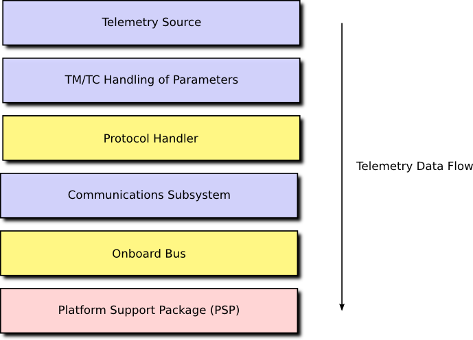
Finally, the system components and libraries of the framework rely on a Platform Support Package (PSP). This is either supplied by us, as part of the FSDK, or by the vendor of the target platform, and contains the basic software routines necessary to access the hardware. In some cases we may provide modifications or patches to vendor-supplied libraries to help integrate the library with our onboard software architecture.
A high-level depiction of the architecture, showing the relationship between the various elements, is presented in Figure 1.

This architecture is perhaps best illustrated with some examples. Typical application layer components would include:
-
subsystem components, which each provide a high-level functional interface to a single spacecraft subsystem such as the EPS;
-
the data pool of key parameter values;
-
data handling components, such as samplers, monitors, and data loggers;
-
telemetry/telecommand (TM/TC) components which provide an interface between the various application components and the communications systems to ground.
In order to send telemetry, a TM/TC component would place the necessary data in a buffer and request that it be transferred using, for example, the Packet Service (PS). The service handler for PS will map this request onto, again for example, a system component acting as a protocol handler. This protocol handler will typically package the data into a valid packet and then send this new packet to the communications subsystem component, again using PS. The communications subsystem component will then transfer the data to the actual hardware using PS or the Memory Access Service (MAS). The service handler will map this request onto a system component providing access to the hardware interface to the device, such an onboard communications bus. The actual interface to the bus is typically provided by functions in the PSP. This sequence of interactions forms a communications stack where the interaction between each element of the stack is via a communications service such as PS or MAS. This is shown in Figure 2.
The communications services, PS and MAS, provide a regular interface to the functional services of other components without requiring knowledge of those components. The use of services in this way means that any component in the stack can be replaced without affecting any other component. This allows you to move your software between platforms easily.
2.2.2. Components and Containers
A component is simply a collection of functions which are centred around two things:
-
parameters, which are the various elements of data associated with the component; and
-
actions, which are the various operations that may be performed on the component.
Our components follow the principles of Object-Oriented Programming (OOP), so parameters are mostly the same as fields or attributes, and actions are mostly the same as methods or routines. Each action is implemented in a single C function. Each parameter is implemented through a number of C functions, called accessors, which provide access to the underlying data. The parameters and actions of a component may be accessed directly, by calling these functions, but they may also be access generically by using an identifier. These identifiers provide a mechanism through which component functionality can be accessed from ground via telecommand.
Every parameter and action in the system is assigned a unique ID, these IDs are mapped onto the action and parameter accessor functions of a component by a simple set of wrapper functions known as the component action source and parameter source respectively. The action and parameter sources translate between ID-based requests and the specific functions of a component. As such, these functions wrap-up access to the component and form part of a component’s container.
A container may also permit access to a component’s functions via a service provider interface, such as a Packet Service provider. This allows the component to be registered with, for example, PS. A request to send a packet using PS, on a specific channel, will then be routed by the PS service handler to a standard interface provided by a component container. This will then invoke an underlying action on the component itself.
As well as providing regular access to a component’s actions and parameters, a container helps manage the life-cycle of a component: component start-up, or initialisation, and component shut-down, or finalisation. A component may also wish to store part of its internal configuration data persistently, to permit the system to return to a previous configuration after a restart. The component’s container will provide functions to ease the handling of his configuration data.
Application and system components are identical, except for the fact that system components do not provide access to actions and parameters via sources.
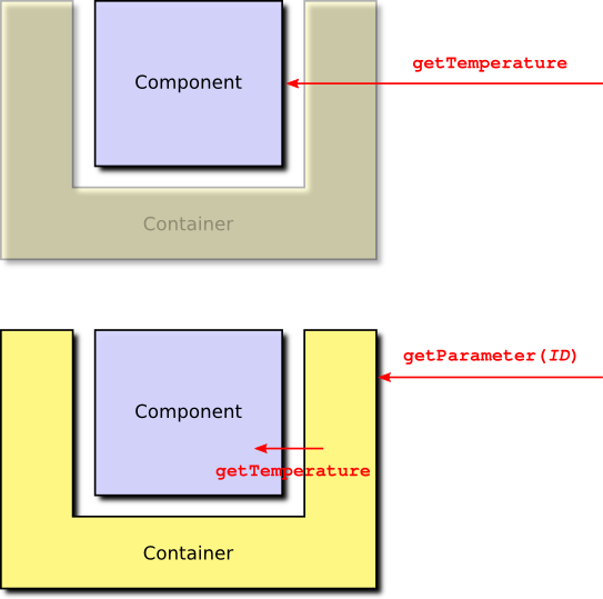
For example, consider a subsystem component which provides a temperature parameter. As this parameter is read-only (in the absence of, for example, heaters, it makes no sense to be able to modify a subsystem temperature) the component needs to provide a single accessor function called getTemperature. If temperature is accessed directly, getTemperature can be used. If temperature is accessed by ID, the container functions of the parameter source are used to translate the ID-based access into a call to getTemperature. This is shown in Figure 3.
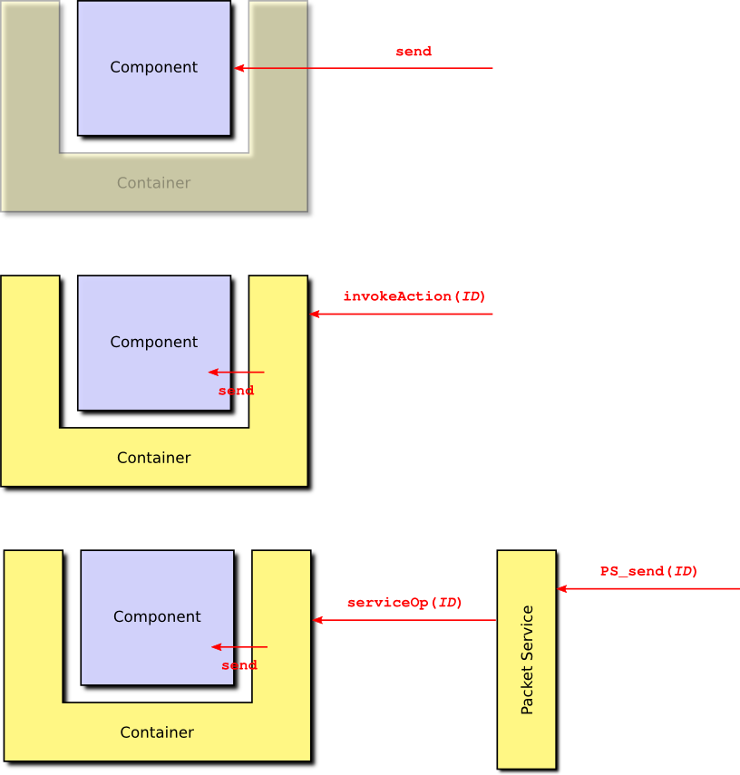
Similarly, an action function, such as send, may be accessed directly, or it may be accessed using an ID, via the action source in the container. The component may also permit access to send using the packet service, in which case another component would invoke a packet service function which accesses the component container which then invokes the component send function. These three cases are shown in Figure 4.
A component which simply responds to requests from other components is known as a passive component. A component may also provide one or more task functions. These are functions which may be attached to, or called called from, a dedicated task. This gives the component its own thread of execution, in which case the component is known as an active component.
2.2.3. Deployments
When writing the code for a component you are actually creating a component type. This is much like a class in OOP. It provides the template for one or more component instances, in a similar way that a class is the template for one or more objects. To create some executing software it is necessary to instantiate a number of components and connect them together. This is called a deployment.
A deployment specifies:
-
what components there will be in the system and how they will each be configured;
-
how the parameters and actions provided by each container may be accessed globally;
-
how the service operations provided by each container may be accessed globally; and
-
the tasks that are related to the component in this deployment and which component task functions they are attached to.
Deployments are specific to a given platform and contain the initialisation code necessary to get the underlying platform up and running. Once the platform is running, the deployment initialises the component manager which is responsible for managing the life cycle of all components (initialisation, configuration and finalisation) and their attached tasks. The deployment then initialises the various services. The component manager then continues by initialising all components. The initialisation process is broken down into three phases:
-
container initialisation;
-
internal component initialisation; and
-
inter-component initialisation, initialising the connections between components or between components and services.
Once the components are initialised, the component manager initialises component tasks. Finally, the deployment permits the task library to begin executing tasks and the component-based system springs into life!
2.2.4. Development Process
The development of any onboard software using the GenerationOne FSDK is likely to follow the same general pattern. Rapid onboard software development, particularly for nano and small satellites, is likely to be collaborative and iterative. We have therefore tried to design the GenerationOne FSDK to support the iterative refinement of onboard software as much as possible.
-
The first step is to identify the major hardware elements of your spacecraft and how those will be represented in software. It is likely that the FSDK will already have some support for your hardware subsystems, but more exotic hardware, especially payloads, may require custom components.
-
Next it is important to identify your concept of operations. How do you want to operate your spacecraft? What does it need to do autonomously? How much data does it need to store and under what conditions? Answering these questions will help you decide what application layer components are necessary and how they should be connected.
-
You’re now ready for a first cut of your onboard software. Using an example deployment as a starting point you can now deploy components to match your spacecraft subsystems and operational concept.
-
Time to try it. Build your deployment and either deploy it onto your hardware, or if you have chosen to target Linux, it will be ready to execute on your workstation. The TMTC Lab graphical user interface can now be used to interact with your onboard software and test its functionality.
-
Identify places where the existing components do not fulfil your mission needs. That might be in areas like mode management, which is typically mission specific, or interfacing to your payload.
-
Design one or more components to meet your needs and describe the interface to each component type in an XML file. You can use the XML files for existing component types as a guide. Once you have a complete interface, use the container generator to generate container code and initial stubs for all component functions.
-
You can now start to populate your new component types with code. You may find it useful to use the unit test framework included with the FSDK to test your components before deploying them.
-
Add your new components to your deployment, rebuild, execute and test!
This process can be repeated as often, and rapidly, as desired for your mission development process.
2.2.5. Basic anatomy of a Component
This section gives an overview of what the different elements are that make up a component. Some of these elements appear in all components, others will appear depending on the design of a specific component.
2.2.5.1. Life-cycle
The most important element deals with the life-cycle of the component, handling the initialisation and the finalisation stages. These are split up between internal initialisation and inter-component initialisation and then inter-component finalisation and internal finalisation. The internal stage is used to set up a valid initial state where all the components can be initialised properly before they are connected. After this, the inter-component connections can be made, which can include the initialisation stage having access to other components. All components have local initialisation and finalisation; inter-component initialisation and finalisation are optional, and can be included if the component has links to other components, or services, which need initialising and finalising.
2.2.5.2. Configuration
The configuration is a system-wide store into which each component can choose to add information about its own, internal, state or configuration. The configuration is usually persistent (e.g. in FLASH), and is typically used to make sure that the configuration of an OBSW system is maintained even if the computer reboots. Every component can choose how much, and what, information to store in its configuration. At initialisation time, each component is asked how much configuration space it needs, the configuration manager then reserves that amount of space in the system configuration. Once the system is running, a component cannot request more configuration space, it must always keep within the value it provided during initialisation. If configuration is used by the component, it will provide functions to allow the configuration manager to request the current configuration of the component, and to set the current configuration. In a special case, if a request is made to set the component’s configuration from a data buffer with a size of zero, the component is expected to re-initialise its configuration to default settings.
Components do not have to use a configuration; if they choose not to, then the configuration elements of the component interface are not present.
2.2.5.3. Tasks
As well as a configuration, a component may also contain tasks. The tasks associated with a component are not created in the component code, instead they are created in a deployment. This puts full control of what tasks there are in the system, and how they are configured, in the hands of the person assembling components, rather than the person writing them. This, in turn, makes components much more reusable.
The component is responsible for supplying the code which will be executed for each task. There are three types of task: periodic tasks, sporadic tasks and interrupt tasks. Periodic task functions are called periodically at intervals defined by their period. Sporadic tasks are called intermittently when they have something to do. Sporadic tasks have an associated data queue and task execution is triggered when something is placed on the queue. Interrupt tasks are used by driver components to respond to low-level hardware interrupts.
The code in a task function is expected to execute, and then return. The next time the period expires (for a periodic task), or there is data on the task queue (for a sporadic task), or the interrupt is asserted (for an interrupt task) the function will be called again. A periodic task function does not contain a loop which waits for the period to expire, that is handled by the task itself. Similarly, a sporadic task function does not block waiting for more data, the task itself handles that.
2.2.5.4. Actions and Parameters
The most elements of a component are the action handlers and parameter accessors that it provides.
Action handlers are very simple: they are functions which are called when an action is invoked either on board or from ground. The simplest actions take no arguments. Alternatively, an action can take a single argument which is always a string of bytes. This argument will always be transferred from the invoker (e.g. ground) with no correction for byte order as is done for parameter values. The argument can either be of fixed length, or it can be of variable length. This means there are three types of action function: those that take no arguments; those that take a single, fixed-length argument; and those that take a single, variable-length argument.
Parameter accessors are called when the value of a parameter is being requested (a 'Get') or being specified (a 'Set') by either another part of the onboard software, or by ground. A read-only parameter will have a get accessor function, in addition to this a read-write parameter will have a set accessor function. As we described in Section Section 2.1.1.2, a parameter can vary in size in one dimension. This variation can either be in the number of rows a vector parameter has, where each row is a fixed size; or in the size of the row, if the parameter is scalar. The type of a parameter determines if the data contained in the parameter can be interpreted as a number, or if it is 'raw' data. This distinction is important, as the framework will automatically convert the byte order (the endianness) of parameters which are numbers when they are transmitted or received to/from ground. The framework will not modify the byte order of raw parameter values. Parameters can have the following types:
-
unsigned integer, with any bit length up to 32-bits supported (referred to as uint);
-
signed integer, with any bit length up to 32-bits supported (referred to as sint);
-
bitfields, with any bit length up to 32-bits supported (referred to as bit);
-
raw values of a fixed size (referred to as raw);
-
raw values of a variable size (referred to as varaw).
All fixed-length types (everything except for variable-length raw values) can be used as either scalar or vector parameters. Variable-length raw values can only be scalar parameters. The first three types, unsigned and signed integers and bitfields, are all treated as number, or value, types. These are the ones that the framework does automatic byte-order conversions on.
3. FSDK Installation
This chapter describes system requirements and installation steps needed to use the FSDK natively on your machine.
Note that we also supply a virtual machine on which the FSDK is pre-installed. This may be run on a variety of host systems using VirtualBox, and is often useful for the first steps in using the FSDK.
If you plan on using the virtual machine you can skip straight to Section 4.
3.1. System Requirements
We have developed and tested the FSDK on Linux, specifically Ubuntu 18.04 LTS. It is likely that other Linux distributions can be used, but this has not been extensively tested and we are not be able to support other distributions in general. Using the GenerationOne FSDK on Windows requires the installation of a Unix-style environment such as Cygwin.
3.1.1. Build Tools
The following tools are required for building GenerationOne onboard software:
-
GNU make;
-
a gcc toolchain targeting your platform, we provide toolchains for some target platforms (e.g. ACS Kryten);
-
the following commands/utilities: echo, find, grep, mkdir, rm, sed, tail, tee, touch;
-
ruby 1.8 or greater to support unit testing;
-
doxygen for building API documentation.
3.1.2. Development Tools
A core part of the FSDK is the code generation tool, codegen, which is used in many different tasks in the FSDK workflow.
codegen is run from the command line, and Java 11 is required to run it.
3.1.3. Ground Tools
Java 11 is required to run TMTC Lab. Specifically Java SE 11.0.13 or later is recommended. There are no other requirements for TMTC Lab.
The Python API requires Python version >=3.7. See the HTML Python documentation (GNDSW/python/doc/html/index.html) for installation and usage details.
3.2. Installation
Installation is primarily a matter of copying all files from the installation media to a suitable location on your workstation. After that:
-
toolchains, if required, should be expanded and placed somewhere suitable (e.g. /opt), ensuring that the binary sub-directory is on the path;
-
Unity and CMock, used by our unit testing framework, should be installed. See Section 3.2.1; and
-
the
codegentooling should be installed. See Section 3.3.
All build scripts use relative path names so the absolute location on your workstation shouldn’t affect your ability to build the software.
3.2.1. Unity and CMock
Our unit testing framework is based the tools Unity and CMock from throwtheswitch.org. We distribute patched versions of these tools under the OBSW/Tools directory.
To extract and install the tools, run the following commands from this location:
-
Specify a writable location for ruby gems to be installed:
$ export GEM_HOME=$HOME/.gem-
Extract the tools, apply patches, and install the ruby gems:
$ ./extract.sh-
Copy the Unity and CMock source files to the unity library in the Source directory:
$ ./copy2lib.sh3.3. Command-line Tooling Installation
In order to execute the command line tooling (CLI), the Tooling/bin directory should be added to your path. The tooling also comes with a manpage, which can be installed by copying the contents of Tooling/manuals to /usr/local/share/man/man1/, this will require super user permissions.
Once the manuals have been copied into place it is necessary to update the mandb with sudo mandb, again requiring super user permissions.
For convenience we have provided an install script Tooling/install_tooling.sh, which will add the Tooling/bin directory to your path and install the manual pages, prompting for a sudo password when copying the manuals.
Help information can be obtained by executing codegen with the -h or --help argument, or if the manpage has been installed, by running man codegen.
It is assumed that the CLI tooling will be run on a Linux system. For information on how to use the CLI tooling refer to Section 5.
3.4. Directory Structure
The root product directory includes five sub-directories. These are:
-
Documentationcontains documentation for the GenerationOne FSDK describing how to install and use the software. -
GNDSWcontains tools, such as TMTC Lab, to act as a basic ground segment for interacting with onboard software. -
Licencescontains the licence for the GenerationOne FSDK as well as licences for 3rd party libraries used by the FSDK. -
OBSWcontains the onboard software source code comprising platform support packages, the framework, libraries of components and example deployments. Build tools and toolchains for supported platforms are also included here. -
Toolingcontains thecodegentool used during software development with the FSDK.
Most sub-directories contain readme.txt files to give a brief description of their contents and purpose.
The root directory also contains a file named version.txt which uniquely identifies your FSDK software version. The version information is encapsulated in a single version string at the end of the file. If you need to contact us for support, supplying this version string to us will help us track the exact version of all files that you have.
3.4.1. Using external source directories
GenerationOne now supports source code that is not part of the FSDK directory structure by making use of environment variables referenced in a project’s config file.
This is described in Section 7.1.1.
4. Getting Started
This chapter describes how to build and run a sample Linux deployment included with the GenerationOne FSDK. The intention is to give you a practical example of the concepts that have been discussed in Section 2.
If you have installed the FSDK on your own machine, as described in Section 3, you can skip to Section 4.2.
If you have not installed the FSDK on your machine and plan on using the VM instead, you must first carry out the steps given in Section 4.1.
4.1. The Virtual Machine
The virtual machine has been set up to help create a simple entry point for users of the GenerationOne FSDK. It requires the use of VirtualBox, which can be found at https://www.virtualbox.org/wiki/Downloads.
We recommend working with the GenerationOne FSDK through the virtual machine if you aren’t using Ubuntu 18.04 LTS. The supplied virtual machine has been tested on VirtualBox version 6.1.
We also recommend running the virtual machine on a 64-bit host machine as the guest OS is 64-bit. If you are running a 32-bit host, then you may need to make sure that hardware virtualisation is enabled in the system’s BIOS. More information can be found in the VirtualBox FAQs and documentation.
4.1.1. Importing the Virtual Machine
Open up the Oracle VM VirtualBox Manager and click 'File' → 'Import Appliance…'. Find and open the .ova file that came with your release. Now click 'Import' and the GenerationOne FSDK VM should appear on your list of virtual machines. Note that you can import the .ova file directly into VirtualBox. The machine is set up as dual-core, for better compatibility, we advise that you adjust the VM’s settings to maximise the resources that it will use.
4.1.2. Getting Started with the Virtual Machine
With the 'GenerationOne' appliance selected, click 'Start' to start the VM. Note that another copy of this manual can be found on the VM’s desktop. Holding the host key (default is right-ctrl) and pressing 'F' will bring the virtual machine full screen, which we find to be easier to work with, especially where the virtual machine is used on a single desktop of multi-desktop host environment. Other functions for use with VirtualBox can be found in it’s documentation.
The login details for the VM are:
User name: gen1-user
Password: BrightAscension
When you start the VM, you should be presented with a basic desktop which contains:
-
Short-cut to the user manual
-
A launcher icon for starting TMTC Lab
-
A launcher icon for opening the command-line terminal
-
A launcher icon for opening the file system.
The FSDK is used from the command-line terminal, and is available in the `gen1-user’s home directory.
4.1.2.1. Setting Up USB Controllers for Linux Hosts
We have set up the virtual machine to connect to USB devices on the host machine for interfacing directly with onboard computers (you can check the list of configured USB filters in VirtualBox Manager under 'Settings' → 'USB'). To be able to use these devices, the user on the host OS must be in the vboxusers group. Further information on this topic is available in the VirtualBox FAQs and documentation.
4.2. First Steps with the FSDK
You should now have a working FSDK environment - either natively on your own
machine, or through the supplied VM. In this section we guide you through
generating, building and running the demo_linux deplyoment.
This section assumes that you have a basic working knowledge of using the command line.
4.2.1. Building Libraries
When building a project for the first time, you need to call make from that project’s directory. For example, to build the app project:
$ cd gen1/OBSW/Source/app
gen1/OBSW/Source/app$ make
If this is the first time building, make will build all the
dependencies. If the dependencies have already been built, it will only build
the app project itself.
If changes have been made to a dependency, the following command will force the build system to check for changes to `app’s dependencies to check whether it needs to rebuild them:
gen1/OBSW/Source/app$ make forceDepending on the speed of your workstation these builds can take several minutes.
For further information on the build system it’s possible to bring up help:
gen1/OBSW/Source/app$ make helpThis will list the valid build configurations for the library. These specify which OS and board the build will target, and can be used on the command-line like so:
gen1/OBSW/Source/app$ make force CONFIG=kryten_failsafe4.2.2. Running Unit Tests
The build system can build and run unit tests as well. The make
command will build all unit tests for the library, and these can be run after
the command completes.
For example, to run the test for the CSLEPS component, run the following binary:
gen1/OBSW/Source/app$ bin/linux/testCSLEPSThe test should execute and the last line of the test output should say 'OK'.
The line before that gives a summary of the test results. Binary executable
files for all unit tests are in the bin subdirectory.
Note that tests include checks that components fail correctly, so there may also be error logs, but this is normal. Look for the Unity output in the console, which should look similar to this:
-----------------------
279 Tests 0 Failures 0 Ignored
OK
The build system can also specifically build and run unit tests. To build all tests:
gen1/OBSW/Source/app$ make testsTo build and run all tests:
gen1/OBSW/Source/app$ make testrunTo build a single test, in this case for the CSLEPS component:
gen1/OBSW/Source/app$ make testCSLEPSTo build and run a single test, in this case for the CSLEPS component:
gen1/OBSW/Source/app$ make testrunCSLEPS4.2.3. Generating Doxygen Documentation
The FSDK source code is commented with extra tags to permit the generation of cross-referenced documentation using Doxygen. You will need to make sure you have Doxygen installed and on your PATH to generate this documentation.
gen1/OBSW/Source/app$ make doxThe build system will invoke Doxygen for the application component source tree. HTML documentation will be produced; you can find the output in the doc subdirectory. Doxygen generates a great deal of output; start with the file called index.html.
Equivalent documentation can be generated for any library in the FSDK.
4.2.4. Generating the Spacecraft Database
The spacecraft database is used by the TMTCLab ground software to communicate with the deployment we are going to run.
Generating an SCDB requires the use of the codegen tool on the command-line.
gen1/OBSW/Source/app$ cd ..gen1/OBSW/Source$ codegen deployment generate demo_linuxSection 5 describes the FSDK’s command line tooling in more detail.
4.2.5. Building the Sample Deployment
Having built the supporting libraries, you can now build the sample Linux deployment. This is in the demo_linux directory and can be built just as with the libraries:
gen1/OBSW/Source$ cd demo_linuxgen1/OBSW/Source/demo_linux$ makeNote that this command will not build dependencies. To check all the dependencies of a deployment, and build them if needed, run:
gen1/OBSW/Source/demo_linux$ make force targetIn either case, the build script follows the same pattern as before, but this time an executable is generated: bin/linux/demo_linux. This is the deployment, and is ready to be executed.
4.2.6. Starting the TMTC Lab Software
TMTC Lab is included as part of the FSDK as an executable JAR file. In some environments you may be able to double-click the JAR file to start the software. Otherwise, you may need to start it from the command line:
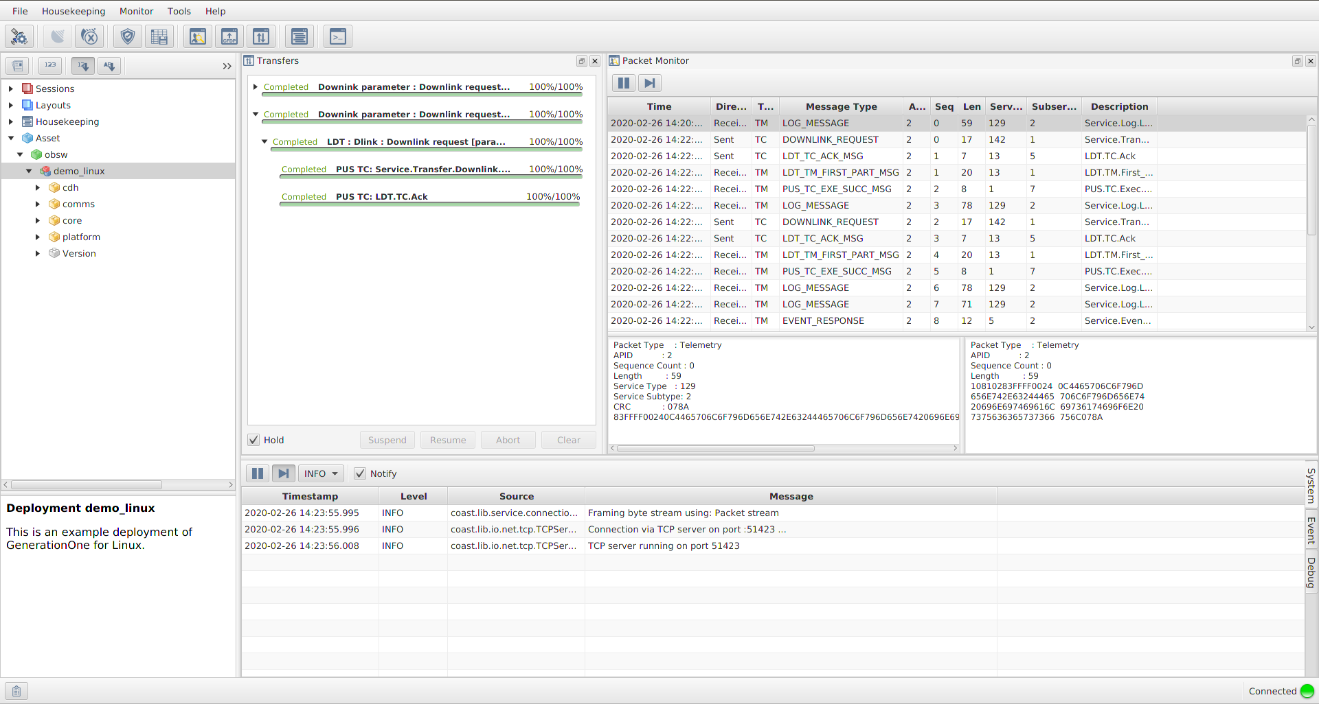
gen1/GNDSW/TMTCLab$ ./runLab.cmdThis should launch the TMTC Lab software and display the main window. The TMTC Lab main window with open Packet Monitor and Transfer is shown in Figure 5. Adding the option -help will provide information on other options that can be used with the software.
When you have finished using TMTC Lab, it’s best if you close it (or at least disconnect) after you stop the deployment from running. If you don’t do it this way round, various resources to do with the connection between the onboard software and TMTC Lab are not properly freed. You would then not be able to start another deployment immediately, rather you would have to wait for a period of time (usually 5-10 minutes) for Linux to detect a time out and free the resources for you.
The TMTC Lab main window contains smaller windows with different functionalities. In a example on the Figure 5 clockwise from top left these are:
-
the Mission Explorer;
-
the Transfer window, showing finished or in progress transfers;
-
the Packet Monitor window, showing all traffic over the space link, each line represents a packet;
-
the System/Event/Debug Consoles.
Details about TMTCLab functionalities are presented in Section 9.
4.2.7. Running the Deployment
Before running the demo_linux deployment, make sure that TMTCLab TCP server is running as described in Section 6.3.5.
To run the deployment from the command line simply execute the binary file we built earlier:
gen1/OBSW/Source/demo_linux$ bin/linux/demo_linuxThe deployment will show various messages showing that it is starting up and configuring various aspects of the system. It will not return so runs indefinitely. You can stop the execution of the deployment using CTRL-C on the command line.
demo_linux uses a TCP client and the initialisation data matches the defaults of TMTC Lab and as such, it should connect successfully.
4.2.8. Basic Telecommanding via Spacecraft Database
The TMTC Lab main window can be used to communicate with the deployment. There is an in-depth chapter on TMTC Lab in Section 9. For now, we will cover basic connection and telecommanding.
In order to communicate with the deployment we need to open the SCDB. This is done as follows:
-
Click 'File' → 'Manage deployments…'
-
Select the top row of the table, then click 'Set deployment…'
-
Set the 'Definition file' to be the
deployment.scdbfile you generated earlier. -
Click 'Open'
-
Close the 'Deployment Management' window
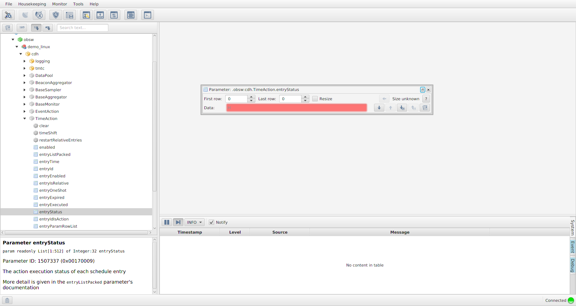
You should be greeted with a window that looks like Figure 6. From here, you can explore the deployment as demonstrated in the image. There are dummy components included in the demo_linux deployment that you can use to get familiar with the interface. If you open the DummySubsys1 tab you will see there’s an action called 'reset' and 3 parameters that hold 8, 16 and 32 bit numbers. If you select the dummyparam8 parameter, you will see it’s signature, ID and a description. There are also Get and Set buttons available. If you click Get, you should see '08' appear in the 'Data' section and also the text 'Parameter accessed successfully' near the bottom. If you change the value to a different number and hit set, you should see the same output text. If you clear the data field and click Get again, it should return the value that you set.
If you now select the 'reset' Action you will see that the interface has changed slightly. Again, you are presented with the signature, ID and a description of the action. You are now able to 'Invoke' an action. Note that there is a disabled argument field; It is here that you would pass in arguments to be used during an invoke. If you click Invoke, the values of the dummySubsys1 component should be reset. You can check this by returning to dummyparam8 and clicking Get, it should return the value '08' again.
TMTC Lab is still running behind the SCDB window, you can minimise it by clicking the icon in the top-right corner. Doing this should reveal that there are now packet logs in the Packet Monitor window. These should mimic the actions that you just under-took while interacting with the deployment. As mentioned in Section 4.2.6, you should only disconnect from the packet service after stopping the deployment when you wish to stop using the TMTC Lab.
4.2.9. Downlink/Uplink Transfers
For each parameter you can get its value or downlink it. If the parameter is not read only, you can also uplink a value from the file. Progess might be followed in window 'Transfers' opened by clicking one of the buttons on the top. Example of Transacation Window after downlink and uplink is presented in the Figure 7.

5. Command-line Tooling
This chapter describes how to use the command-line tooling to generate FSDK code and projects. The CLI tooling is currently capable of generating new Component Types, Deployments and Libraries as well as generating source code and documentation for Component Types, Services, Libraries and Deployments. This section assumes some confidence in using the command line, see Section 3.3 for installation instructions.
5.1. Usage
The CLI program follows a common usage pattern:
$ codegen [codegen-type] [operation] [path] [options]In general the codegen command takes three positional arguments, followed by zero or more optional arguments. The first positional argument is the type of code generator you wish to use, the valid options are as follows:
componenttype, service, library or deploymentThe second positional argument is the operation you wish to perform on the code generator type:
-
generate: generate code and documentation -
generate-code: generates code only -
generate-docs: generates documentation only -
new: creates a new instance of the chosen type
The third positional argument is the target PATH and is relative to your current working directory. The PATH can be a full path to a target input xml, such as a componentType.xml or to the project folder e.g. path/to/MyDeployment/.
5.1.1. Optional Arguments Table
The following table lists all available optional arguments along with a brief description of what they do, for more detailed information you can look at the manual provided with GenerationOne by typing man codegen.
| Arg | Shorthand | Valid Codegen Types | Description |
|---|---|---|---|
--name |
-n |
componenttype, service |
The fully qualified name of the target unit type |
--unprotected |
-k |
componenttype |
Whether or not component type generates with protection lock |
--value-storage |
-s |
componenttype |
Whether or not component type generates with value storage |
--unit-tests |
-t |
componenttype |
Whether or not unit tests are generated |
--force |
-f |
any |
Force generation of all files, overwriting any files on disk |
--regenerate-all |
-a |
componenttype |
Regenerate all containers in a given directory |
--dry-run |
-d |
any |
Dry-run, shows files that would be generated without actually creating them |
--remove-unused |
-r |
deployment |
Clean files that will not be part of file generation list |
--board-specific |
-b |
componenttype, service, library |
Specifies the unit type is board specific |
--os-specific |
-o |
componenttype, service, library |
Specifies the unit type is operating system specific |
--build-config |
-c |
any |
Specifies the build configuration to use |
--help |
-h |
any |
Show command help information |
--verbose |
-v |
any |
Increase verbosity level |
--version |
N/A |
any |
Show version information |
5.2. Usage Examples
This subsection will cover how to use each of the code generator commands in more detail along with examples.
5.2.1. Component Types
The following command will generate a new Component Type xml in a library project:
$ codegen componenttype new my_library --name MyComponentTypeThere are multiple ways of generating existing Component Types. Platform independent Component Types can be generated by specifying the path to the componentType.xml or specifying the project and the fully qualified name of the Component Type.
This example uses the Dummy Component Type present in the app project.
$ codegen componenttype generate app/inc/Dummy

$ codegen componenttype generate app --name Dummy
It is also possible to specify that a new Component Type should be platform specific by providing a build configuration along with whether the Component Type is board or operating system specific. The codegen tool will then look up the correct build configuration and extract the architecture information needed to generate. The following example shows how to generate the board specific RTC Component Type.
$ codegen componenttype generate framework/arch/csl_obc/inc/io/driver/RTC

$ codegen componenttype generate framework --name RTC --build-config csl_obc
5.2.2. Services
Services are generated in a similar way to Component Types and are generally platform independent. Similar to Component Types, you can either specify the path to the service.xml or specify the project and the fully qualified name of the Service.
$ codegen service generate framework/inc/io/FSS

$ codegen service generate framework --name io.FSS
5.2.3. Libraries
A new library project can also be created using the codegen tooling. New projects should be created in the root of the OBSW/Source directory. The following command will create a new library project called 'my_library'.
$ codegen library new my_libraryExisting library projects can be generated as follows:
$ codegen library generate my_library5.2.4. Deployments
A new deployment can also be created using the codegen tooling. New deployments should be created in the root of the OBSW/Source directory. The following command will create a new deployment called 'my_deployment'.
$ codegen deployment new my_deploymentTo generate code and documentation, including the Spacecraft Database for an existing deployment:
$ codegen deployment generate my_deploymentIt is also possible to simply regenerate the Spacecraft Database and documentation for a given deployment by specifying the
generate-docs operation.
$ codgen deployment generate-docs my_deploymentIf a deployment should be generated with a different build configuration to the default specified in the project.mk then
you may pass in a different build configuration.
$ codegen deployment generate my_deployment --build-config csl_obc6. Working with a Deployment
This section will take you through how to set up a GenerationOne FSDK deployment. It will show you the initial set up and then how to add new components to a deployment specification before then showing you how to generate code for that deployment and add in the initialisation data. The chapter will help take you through the different options that you will come across while working with an FSDK deployment.
The chapter will take you through the different parts of a deployment step by step. The final result is available in the gen1/OBSW/Source/legacy_tutorial1 directory.
6.1. Setting Up a New Deployment Project
To set up a project to create your deployment in, navigate to the OBSW/Source directory using the terminal, and execute the following codegen command:
$ codegen deployment new <name-of-deployment>This will generate a new project directory using the name you provided, containing all the files and directories necessary for creating your own deployment:
-
Makefile
-
config directory
-
project.mk
-
-
inc directory
-
src directory
-
deployment.xml
6.2. Deployment XML Model
The next step involves defining the deployment XML model within the deployment.xml file.
The deployment XML model follows a similar structure to the component XML, as you’ll find in the next chapter. It describes the structure of the deployment that you want to build, including what components to include as well as describing how various component instances connect to one another.
A good starting point for this is to reuse an existing model, and modify it to fit your needs. Copy the contents of the demo_linux deployment’s deloyment.xml file, and paste them within the deployment.xml file in your newly created project. Replace the name parameter in the Deployment section of the file with your project’s name and update any comments as required.
A large portion of the XML taken from the demo_linux project consists of setting up the communications stack. This is a list of connected components that describe how to collect and respond to telecommands and how to create and send telemetry. For the basic demo_linux deployment, we don’t need to add anything else to create a functional deployment. Similarly, the majority of the following tutorial doesn’t require any adjustments to the communications stack, although there is an extra section added as a reference point.
Similar to #includes in C, you need to identify the component types that are used in a deployment, and this is done in the import section. Unlike the deploy section that follows, the order in which components are imported is not important. For ease of navigation, we find it simplest to keep both lists in the same order.
Following the import section is the deploy section. This section defines both groups that are used in the deployment structure and each of the component instances in your deployment.
Before defining the component instances, component groups can be defined. It is not necessary to define every group used in a deployment, but defining a group allows for documentation to be added, which can help when searching for specific component instances.
After defining component groups, you define the component instances. The order in which the component instances are specified defines the order in which each instance is initialised. For each instance to be deployed, you need to describe the component type and then the name that you want to use to refer to that particular instance. In most cases, you may wish to name the instance the same as it’s component type. However being able to name different components allows you to give more meaningful names to components if you have multiple instances. We’ll come across such a case later on.
For this tutorial, we will start off by adding a simple component instance to the deployment’s XML. After that, we can move onto generating the deployment code and then filling out the initialisation data for this component before building the deployment and then interacting with the component through the TMTC Lab application.
The first component we’ll add is another dummy subsystem. A dummy subsystem component is a component that can be used for simple testing by holding parameters that can be set and retrieved.
To add a component to a deployment, you need to specify that it is to be used in the Import list, and then add it to the Deploy list. You’ll see that in the import list, Dummy is already being used. Scroll down in the Deploy section until you reach the component named 'platform.DummySubsys1'. Below this component, add a new one called 'platform.DummySubsys2'. The 'platform' before the name 'DummySubsys1' indicates to the code generation tool that the component instance should reside within the 'platform' component group. Component groups can be nested, for example 'cdh.tmtc.TMBeacon' would place the TMBeacon component instance into the cdh/tmtc/ group.
<Component name="platform.DummySubsys1" type="Dummy" />
<Component name="platform.DummySubsys2" type="Dummy" />
As DummySubsys is a simple component, nothing more is needed to include the instance in the deployment. Once the XML is complete, the deployment code can be generated.
6.3. Generating a Deployment
6.3.1. Code Generation
To generate the deployment navigate to the OBSW/Source directory using the terminal, and execute the following codegen command, replacing <name-of-deployment> with your project name:
codegen deployment generate <name-of-deployment>This should have generated various new files and directories within the inc and src directories. Both directories now contain a deploy directory and an init directory. These are where deployment and initialisation data are handled respectively. There is also a deployment directory generated in src, this file provides the entry point for the deployment stage of the build system. The inc directory and src/deploy directory contain deployment generated code and should not be edited directly as they may accidentally be overwritten if the deployment is regenerated.
As with component generation (discussed in Section 8), there are files that are generated initially which can then be filled out by you. For deployments, these files are the initialisation source files located in src/init. If you change the group that a component instance is in, be sure to remove the old files (as they won’t be deleted) and to move/update the init file.
The next step after generating the deployment is to set up the initialisation data.
6.3.2. Component Initialisation Data
There are quite a number of components to initialise, most of which would require a more in depth understanding of the GenerationOne FSDK. To keep things simple for now, we will replace the generated initialisation source with the one from demo_linux. Simply copy and replace from demo_linux/src/init to your deployment project’s equivalent directory.
This should overwrite the duplicate files and leave just the additional dummy component to initialise. Using 'DummySubsys1' as a guide, fill out the initialisation data for 'DummySubsys2'.
With the initialisation data set, you can build and run your deployment.
6.3.3. Building a Deployment
Before attempting to build the deployment we first need to make sure the project.mk file is configured properly. Since we are building this deployment to run on a linux machine we need to specify this using the VALID_CONFIGS parameter. Assign VALID_CONFIGS the value linux, then save your changes. In addition, you will also want to make sure that the list of dependencies specified by DEPEND_DIRS is correct, according to the components you are including in your deployment. Since our deployment only contains components from the app and framework libraries, we can leave this as is. Once the project.mk file has been updated, we can build the deployment using similar steps to those for building a library (in Section 4.2.1). It should build without any errors. If there are errors, retrace the previous steps.
6.3.4. Building a Spacecraft Database
The Spacecraft Database is used to interact with a deployment using TMTC Lab, as seen in Section 4.2.8.
The Spacecraft Database is generated as part of a deployment generation step above, however it is possible to generate only the Spacecraft Database without generating deployment code. This is achieved using the codegen tool.
To generate the database standalone navigate to the OBSW/Source directory using the terminal, and execute the following command:
$ codegen deployment generate-docs <name-of-deployment>This generates a deployment.scdb file which it places within a directory named doc. This file will be used by TMTCLab to enable interaction with the spacecraft.
6.3.5. Interacting With a Deployment Using TMTCLab
The deployment should be using a TCP client and so you’ll need to set the TCP server to connect to, which TMTC Lab can be used for. TMTC Lab can be run by executing the runLab.cmd script in the GNDSW/Source/TMTCLab/ directory. You should be greeted with a pop-up saying 'Connect to onboard software' followed by a TCP port. This is explained further in Section 9.2.3. The default settings should be valid so just click 'Connect'.
Now that the TCP server is running, you can run your deployment and interact with it. Since our deployment is built to run on linux we can simply run it directly from the terminal. To run the deployment navigate to OBSW/Source/<name-of-deployment>/bin/linux and execute the following command:
$ ./<name-of-deployment>You should see output in the console similar to below.
INF: arch/posix/src/Main.c:67 Platform initialisation successfulIn the Debug console window in TMTC Lab (Section 9.1.3.3) you should see that the deployment initialisation was also successful. Additionally, there may be some debug output regarding the deployment overwriting data, this is just the deployment setting up storage channels used by the loggers.
As mentioned previously, we’ll be interacting with the deployment using the generated spacecraft database. There is a section later on (Section 9.1.1) which goes into a more in depth view of using the Mission Explorer and TMTC Lab in general. For now, we’ll look at what we need to interact with the deployment.
-
Click 'File' → 'Manage deployments…'
-
Select the top row of the table, then click 'Set deployment…'
-
Set the 'Definition file' to be the
deployment.scdbfile you generated earlier. -
Click 'Open'
-
Close the 'Deployment Management' window. This should bring up the spacecraft database in the 'Mission Explorer' window on the left hand side of the GUI. Here, under your mission you’ll see a list of all the component groups with the component instances inside that you added to the deployment.
-
Open up the
platform.DummySubsys2component. You should see an action called 'Reset' and the three parameters that you set up in the initialisation data. -
Select one of the parameters and then press the 'Get' button that should have presented itself next to the list.
-
You should find that the hexadecimal value returned matches the one that you had set in the initialisation data. Click on letter 'H' to change values to decimal or binary numbers. The same will hold true for the other parameters.
-
You can also set the parameters which will change the stored value.
-
Finally, if you invoke the 'Reset' action, you should find that the parameters have returned to their initial values.
When you have finished using TMTC Lab, first disconnect the deployment (by stopping it from running) before disconnecting the packet server ('Connection' → 'Disconnect') to free up the TCP port.
6.4. Data Handling for Deployment Components
When you have a component in your deployment, you may wish to perform some data handling on the parameters that are accessible.
6.4.1. Adding to the Data Pool and Sampler
A common requirement of onboard software is to cache parameter data in a data pool. The GenerationOne FSDK provides the DataPool component to do this. A Sampler component is then used to periodically update particular parameters in the data pool. This is discussed in detail in Section 2.1.4.1 and Section 2.1.4.2.
Going back to the deployment.xml file, you should find that the DataPool component already has DummySubsys1 added to it. Add the DummySubsys2 component instance underneath the first one and give it a name to access it with (usually the same name as the instance).
Accessor defines will be generated for each parameter in the data pool. The individual parameters that we want to store in the datapool are specified here. It is possible to omit the parameter field, which will cause the datapool to generate parameters for each corresponding parameter for a component. We don’t want this for the Dummy component, because it’s dummyBuffer parameter has 65535 rows, which is a lot of data to cache, and unnecessary for this demonstration. As well as avoiding particularly large parameters, there may only be a few parameters which need to be pooled.
<Component name="cdh.DataPool" type="DataPool">
  <ParameterAliases>
    <ParameterBlock blockName="poolParameters">
      <ComponentParameter name="DummySubsys1"
		          component="platform.DummySubsys1"
		          parameter="dummyParam8" />
      <ComponentParameter name="DummySubsys1"
		          component="platform.DummySubsys1"
		          parameter="dummyParam16" />
      <ComponentParameter name="DummySubsys1"
		          component="platform.DummySubsys1"
		          parameter="dummyParam32" />
      <ComponentParameter name="DummySubsys2"
		          component="platform.DummySubsys2"
		          parameter="dummyParam8" />
      <ComponentParameter name="DummySubsys2"
		          component="platform.DummySubsys2"
		          parameter="dummyParam16" />
      <ComponentParameter name="DummySubsys2"
		          component="platform.DummySubsys2"
		          parameter="dummyParam32" />
    </ParameterBlock>
  </ParameterAliases>
</Component>
6.4.1.1. DataPool LifeTime
While that will set up the DataPool component, there is also an optional connection to include an OBT component. Adding this time component will allow the DataPool component to determine whether pooled parameters can be considered expired, based on the DataPool’s lifeTime parameter. If it expires, then reading a pooled parameter will cause the DataPool to read through to update it’s value. To use this, add this before the ParameterAliases tag:
<Connections><Services>
    <Service name="time" component="core.Time" service="time"/>
</Services></Connections>
6.4.1.2. Setting up the Sampler
The Sampler component is already set up, it just needs to know which data pool parameters it should update. As the Sampler uses a periodic task, this also needs to be set up. Periodic tasks need three things to be set up:
-
the name of the task in the source,
-
which is found in the library documentation;
-
-
the period for the task in seconds,
-
which is currently set to 5 seconds;
-
-
and the priority for the task while running on the operating system.
Generate the deployment again and note that all but the src/init directory is updated. This stops you from accidentally overwriting extensive initialisation data that you may have set-up. Indeed, we don’t want to overwrite what’s already there, we’ll instead be adding to the initialisation data.
Open up DataPool_Deploy.h and you should find that some defines have been generated. As well as accessors for DummySubsys1 parameter aliases, there are now some for DummySubsys2 Now in BaseSampler_Init.c, add in these additional parameter defines to the array that currently contains DummySubsys1’s.
static const ui16_t gru16_BaseSamplerParamList[] =
    {
        DEPLOY_CDH_DATAPOOL_PARAM_ALIAS_INDEX_DUMMYSUBSYS1_DUMMY_PARAM32,
        DEPLOY_CDH_DATAPOOL_PARAM_ALIAS_INDEX_DUMMYSUBSYS1_DUMMY_PARAM16,
        DEPLOY_CDH_DATAPOOL_PARAM_ALIAS_INDEX_DUMMYSUBSYS1_DUMMY_PARAM8,
        DEPLOY_CDH_DATAPOOL_PARAM_ALIAS_INDEX_DUMMYSUBSYS2_DUMMY_PARAM32,
        DEPLOY_CDH_DATAPOOL_PARAM_ALIAS_INDEX_DUMMYSUBSYS2_DUMMY_PARAM16,
        DEPLOY_CDH_DATAPOOL_PARAM_ALIAS_INDEX_DUMMYSUBSYS2_DUMMY_PARAM8,
    };
You can see from the sampler’s initialisation data that it will start off disabled and that its period multiplier is 10, which means it will run its task’s function every tenth call, and so approximately every 50 seconds.
In the spacecraft database explorer in TMTC Lab, enable the base sampler by setting the enabled parameter to 1. This will then start updating the DataPool. You can check this by changing one of the platfom.DummySubsys2 parameters.
6.4.2. Logging and Monitoring Parameters
Another common data handling requirement is to periodically log parameters, through the use of a data logger and also to monitor parameter values, to check that they’re in range. This next tutorial section will take you through how to add a parameter to the base aggregator so that it is logged along with other aggregated data and also how to set up a monitor on a parameter.
6.4.2.1. Adding to an Aggregator for Logging
DataLoggers periodically store a given parameter in a specified data channel. To store multiple parameters, aggregators are used to bit-pack provided parameters into a compact state for logging. The initialisation data for aggregators is similar to that of the other data handling components, and can be edited manually to modify the parameters in the aggregation. There is also the possibility to use the graphical aggregation builder in TMTC Lab to define and modify aggregations, in which case the deployment generation step will create the aggregator initialisation data for you.
As demo_linux uses automatically-generated aggregator definitions, we will first run through the process using TMTC Lab.
-
Generate the latest spacecraft database
-
Open up the spacecraft data in TMTC Lab
-
Launch the aggregation builder by selecting 'Tools' → 'Aggregation builder…'
-
Select the toolbar button for loading a portable definition (a folder with a 'P' on it)
-
Browse to the location of the
demo_linuxdeployment project and into thedefdirectory -
Select the
BaseAggregator.yamlfile and click 'Open'. This will bring up the configuration for the BaseAggregator in the aggregation builder. -
Add
DummySubsys2’spooled parameters by locating them in the main spacecraft tree on the left and dragging them into the aggreation builder, do this with all three of theDummySubsys2pooled parameters to give a total of six parameters. -
You will see that the 'Last Row' for the
DummySubsys1parameters is the value '65535'. This is treated as a special value to indicate that the aggregator should use as many rows as there are available. Set the 'Last Row' on the parameters you just added to '65535'. -
Save the aggregation in portable form (the disk icon with a 'P' on it), overwriting the existing definition.
-
Regenerate the deployment. You should be able to look at the initialisation data in
src/init/cdh/BaseAggregator_Init.cand verify that the new parameters have been added.
Without a YAML file with the same name as the aggregator component in the `def} directory, the initialisation data for the aggregator will not be generated by the deployment code generator. In this case the file can, and should, be edit manually. The equivalent manual process for the steps we went through above is as follows:
-
Open up
src/init/cdh/BaseAggregator_Init.c.-
You should find an array similar to the one in the sampler.
-
As with that component instance, you can add to the array that is used for initialisation data.
-
-
Add
DummySubsys2’sparameters below the elements currently set.-
Follow the example for DummySubsys1’s pooled parameters.
-
As with other parameter IDs, the ID for the pooled parameters can be found in the
inc/Deploy.hfile, though they’re in their own separate section towards the bottom of the file. -
As you can see from the data, you specify not only the parameter to aggregate, but also the row range.
-
For simplicity, you can specify
AGGREGATOR_ALL_ROWSto automatically adjust the end of the range to the last row available. -
This is similar to the behaviour when getting a variable sized parameter with resize on (See Section 9.3.5.8).
-
You can also specify a fixed width for each element, which can help to know the space being taken up.
-
Taking a look at src/init/cdh/logging/BaseLogger_Init.c, you’ll see that the BaseAggregator ID is added as the ID of the parameter for the BaseLogger to log.
You should be able to successfully build the deployment and run it. During the initialisation output, you should see LoggerCore output this debug message:
DBG: src/logging/LoggerCore/LoggerCore.c(111): Channel has incorrect record size, reformatting
This helps confirm that we’ve been able to adjust the aggregator successfully. It shouldn’t appear again if the deployment is run a second time, as the channel should now be correctly formatted.
6.4.2.2. Setting up a Monitor
A monitor allows a deployment to raise a specified event if a parameter goes outside of a given range. To do this, open up src/init/cdh/BaseMonitor_Init.c and then add a new element to the grt_BaseMonitorChecks array using one of the DummySubsys2 parameter alias defined in the data pool. Specify a range that will allow you to set that parameter outside of the range (which is inclusive), for example:
{
        .u16_ParamID = DEPLOY_CDH_PARAM_ALIAS_DATAPOOL_DUMMYSUBSYS2_DUMMY_PARAM16,
        .u16_ParamRow = 0,
        .u32_UpperLimit = 0xBEEF,
        .u32_LowerLimit = 0,
        .u16_FailThreshold = 0,
        .u16_UpperEventID = MONITOR_EVENT_CHECK_FAILED_ERROR,
        .u16_LowerEventID = MONITOR_EVENT_CHECK_FAILED_ERROR,
        .u8_Group = 0,
        .u8_Flags = MONITOR_FLAG_ENABLED_MASK
},
Typically, you’ll want the event ID to be the one shown in the example above as this is the event expected for when monitored values exceed a limit, although it is possible to raise any event available through the deployment.
We’re monitoring the parameter value stored for DummySubsys2 in the DataPool. We could get the parameter directly, in this instance it wouldn’t make much difference. However, if the parameter of a hardware component was to be monitored, it may be more desirable to monitor the value stored in the DataPool than to query the hardware. For this deployment, the monitor runs it’s refresh task every 5 seconds and this is also the rate at which the DataPool is sampled and so it is just as easy to check the DataPool parameter.
As with the addition to the aggregator, you should be able to successfully build and run the deployment.
-
Open up the spacecraft database in TMTC Lab.
-
From the initialisation data, you may have noticed that the monitor initialises as disabled and you can check this by getting the enable parameter.
-
Set the enable parameter to 1
-
the monitor will now be checking the values you set every 5 seconds.
-
-
If you now change your
DummySubsys2parameter to an invalid range-
(with the above example, 0xBEF0 would be out of range)
-
-
you should see within 5 seconds an error message in the output console of Eclipse, informing you that the parameter check failed.
-
This message will only appear once, unless the parameter is made valid and then invalid again.
-
6.4.3. Adding Parameters to the Telemetry Beacon
We’ll now add to the frame that’s transmitted by the TMBeacon component. The beacon transmits frames with individual periods which are relative to the beacon’s task period. The frame transmitted is the parameter from a separate instance of an aggregator; the BeaconAggregator. As with the BaseAggregator, add in some more parameters from DummySubsys2 that you can use to check.
Taking a look at src/init/cdh/tmtc/TMBeacon_Init.c, you can see that there’s a single frame set up to be sent each period and the parameter transmitted is the BeaconAggregator packed data. With the new parameters added to the BeaconAggregator, you should be able to build and run the deployment.
-
Open up the spacecraft database in TMTC Lab.
-
TMBeacon starts off disabled, so set the enable parameter to 1.
-
Once enabled, you should see the beacon frame being received from the packet log in the packet monitor window of TMTC Lab.
-
You should see that on the end of the received beacon frame are the parameters that you added.
-
When you change these values, you should see the changes reflected in newer frames that come in.
6.5. Adding some Automation
As well as components that wait on a user’s input, you can set up automation components that run on set tasks. These components are mainly found in the auto section of app. The one we’ll be looking at is PeriodicAction. A more detailed description of the periodic action component is in Section 2.1.5.4.
We’ll be using this component to reset the data that we’ll be able to see being transmitted by the beacon.
-
This component is already present in the deployment and is grouped with the other auto components:
<Component name="cdh.PeriodicAction" type="auto.PeriodicAction">
  <Tasks>
    <PeriodicTask name="cycle" period="60.0" priority="2"/>
  </Tasks>
</Component>
The periodic action component doesn’t need to be connected to another component, but it does contain a periodic task (as can be found by checking the library documentation).
-
Like the sampler, PeriodicAction requires a periodic task. Here, the name variable refers to the name of the task, for example the `Sampler} task is called 'sample'. This information can again be found in the library documentation. Checking this, you should find that the `PeriodicAction} task name is 'cycle'.
-
Next is the priority of the task, this is used by the operating system when scheduling system tasks, where a low priority number denotes a low priority task.
-
Next we can set the period for the task. This is one of the optional attributes and if there is not set a period, then the default period for component type will be used. We will be using this component to reset the values of some dummy parameters after we’ve set them and seen them get aggregated successfully and then sent by the beacon. As such, we want the period to be relatively large, for example 1 minute.
-
As the deployment was already generated, now you need to open up
src/init/cdh/PeriodicAction_Init.cto complete the initialisation data for the component. Above the initialisation data, add an array (so that you can add more elements later for experimentation) of periodic action entry types and then fill out a single element that will call 'refresh' onDummySubsys2and runs each period. We also want to set flags on the entry to make sure that it’s enabled. -
Next you want to fill out the initialisation data using the array you just created. You could set the entry count to 1, but for ease of appending later, you should pass in the size of the array. We’ll also start with it disabled so that it isn’t running without your knowledge.
You should end up with something that looks similar to the example below (note that you’ll need to include dummy’s action source header):
#include "Deployment.h"
#include "init/cdh/PeriodicAction_Init.h"
#include "auto/PeriodicAction/PeriodicAction.h"
#include "Dummy/Dummy_ActionSrc.h"

/*---------------------------------------------------------------------------*
 * Global variables
 *---------------------------------------------------------------------------*/

/** The entries for the periodic action */
PeriodicAction_Entry_t grt_PeriodicActionInitEntries[] =
{
    {
        .u8_PeriodMultiplier = 1,
        .u8_CurrentPeriod = 0,
        .t_Id =
            DEPLOY_ACTIONSRC_BASE_PLATFORM_DUMMYSUBSYS2 + DUMMY_ACTION_RESET,
        .u8_Flags =
            PERIODICACTION_FLAG_ENABLED_MASK |
            PERIODICACTION_FLAG_IS_ACTION_MASK,
        .u8_ArgumentLength = 0, /* No argument needed for reset */
    }
};

/** The PeriodicAction initialisation data */
const PeriodicAction_Init_t gt_PeriodicActionInit =
    {
        .pt_Entries = &grt_PeriodicActionInitEntries[0],
        .u32_EntryCount =
            sizeof(grt_PeriodicActionInitEntries) /
            sizeof(grt_PeriodicActionInitEntries[0]),
        .b_Enabled = FALSE,
    };
Build and run the deployment and open the spacecraft database in TMTC Lab. Note that you will need to regenerate the spacecraft database as you’ve added PeriodicAction to the deployment.
-
First get one of the parameters of
DummySubsys2to note that it’s the initial value. -
Then set it to something else and set the enable parameter for PeriodicAction to 1.
-
After a minute the parameter that you altered should have been reset to it’s initial value.
-
There may also have been a debug log similar to the one below that will help confirm that the action was called successfully.
DBG: src/Dummy/Dummy.c(253): Dummy reset called
6.6. Adding Hardware Subsystems
This next section will take you through the basic process of adding a hardware subsystem, in this example case a Clyde Space 3rd generation EPS (CSLEPS), as well as how to add a Total Phase Aardvark to act as the I2C master.
6.6.1. Total Phase Aardvark
There is a demonstration deployment for using the Aardvark – demo_aardvark.
The first steps you need to take is to include the aardvark/inc directory into the deployment project. After that, you need to make some additions to the dependencies section of the project.mk file. As well as adding '../aardvark' to the dependencies directories, you need to add 'dl' to the external libraries. This is because the main Aardvark library, Aardvark.so, is loaded dynamically and 'dl' is necessary to support this.
# Dependencies (library directories)
DEPEND_DIRS := ../app ../aardvark ../framework ../posix ../linux ../core
TEST_DEPEND_DIRS := ../unity
EXTERNAL_LIBS := dl pthread rt
6.6.2. Adding to the deployment
Adding the EPS is similar to how other components are added, you just need to specify that the subsys.csl.CSLEPS component is being used in the Import section and then add an instance to the Deploy section.
    <Use type="subsys.csl.CSLEPS" />
      ...
    <Component name="platform.EPS" type="subsys.csl.CSLEPS" />
After that, you need to specify the service that the EPS will use, which is where the Aardvark comes in.
-
The Aardvark resides in the project of the same name and so you want to add
<Use type="io.bus.i2c.AardvarkI2CMaster" />to the import section. -
After that, you want to define an instance of the Aardvark, before the definition of your EPS. Then you can add the service to your EPS and you should end up with something similar to below.
    <Component name="platform.PlatformI2C" type="io.bus.i2c.AardvarkI2CMaster" />
    <Component name="platform.EPS" type="subsys.csl.CSLEPS">
      <Connections><Services>
        <Service name="bus" component="platform.PlatformI2C" service="data" channel="0"/>
      </Services></Connections>
</Component>-
After generating, initialisation stubs will be created for every component instance. The EPS doesn’t need any initialisation data to be set. The Aardvark does however have some initialisation data to set up.
-
Open up the file from
src/init/platform/PlatformI2C_Init.cand enter the following data:
/** The list of channels for the I2C Master */
const AardvarkI2CMaster_Channel_t rt_Channels[] =
{
    {
        /* EPS address */
        .u8_SlaveAddress = 0x2B
    }
};

/** The PlatformI2C initialisation data */
const AardvarkI2CMaster_Init_t gt_PlatformI2CInit =
{
    .u32_DeviceIndex = 0,
    .u8_Address = 0x10,
    .u16_BusSpeed = 100,
    .pt_Channels = rt_Channels,
    .u32_NumOfChannels = sizeof(rt_Channels) / sizeof(rt_Channels[0]),
    .b_AlwaysInit = FALSE
};
Note that in the deployment xml, the EPS uses channel 0 of the service that it’s using. The default channel is 0, so this could have been omitted. However, if there were more subsystems on the I2C bus, those could then be linked to incrementing channels.
The channels correlate to the index in the rt_Channels variable in the Aardvark’s init data. Therefore, any future subsystems which are added can be set up with their respective slave address.
If the EPS was deployed on a different platform, for example the Clyde Space Ltd. OBC, the Aardvark I2C Master component can be swapped out for an I2C driver component which is specific to that platform. The channel value for the required service remains the same, making it easier to deploy platform independent components.
6.6.3. Servicing the EPS Watchdog
One of the uses of the PeriodicAction component is using it’s functionality to service one or more system-wide watchdogs. We’ll demonstrate this by adding the CSLEPS watchdog reset action to the list of actions for the PeriodicAction component instance. This should be simple enough using the other element in the grt_PeriodicActionInitEntries array as a template to get the set up below:
{
    {
        .u8_PeriodMultiplier = 1,
        .u8_CurrentPeriod = 0,
        .t_Id =
            DEPLOY_ACTIONSRC_BASE_PLATFORM_DUMMYSUBSYS2 + DUMMY_ACTION_RESET,
        .u8_Flags =
            PERIODICACTION_FLAG_ENABLED_MASK |
            PERIODICACTION_FLAG_IS_ACTION_MASK,
        .u8_ArgumentLength = 0, /* No argument needed for reset */
    },
    {
        .u8_PeriodMultiplier = 1,
        .u8_CurrentPeriod = 0,
        .t_Id =
            DEPLOY_ACTIONSRC_BASE_PLATFORM_EPS + CSLEPS_ACTION_RESET_WATCH_DOG,
        .u8_Flags =
            PERIODICACTION_FLAG_ENABLED_MASK |
            PERIODICACTION_FLAG_IS_ACTION_MASK,
        .u8_ArgumentLength = 0, /* No argument needed for resetWatchDog */
    },
};
To use the CSLEPS actions, you need to include the relevant header:
#include "subsys/csl/CSLEPS/CSLEPS_ActionSrc.h"Now, once the PeriodicAction instance is enabled, the 3G EPS watchdog will be reset approximately every minute.
6.7. Configuration Management
Included in the demo deployments are configuration stores and configuration management components. A configuration store component can be used for persisting the configuration of your deployment for components that store a configuration. The ConfigManager component can be used to help manage the set up for configuration for a deployment, such as whether configuration is enabled.
Section 2.2.5.2 provides an explanation about configuration from a component’s perspective.
6.7.1. Configuration Store Components
There are various configuration store components available in the GenerationOne FSDK, some of which are platform dependent. For this demonstration, the FileConfigStore component can be used to store a persistent configuration. The FileConfigStore component creates files to store component’s configuration, using a provided file system component’s file service which in this demonstration is provided via the POSIX OS. In the initialisation data for the component, it is possible to set the limit for how many different system configurations there can be.
Other configuration store components are available:
-
FlashConfigStore– This stores system configuration across flash pages, with the number of configurations supported being dependent on the amount of memory available. This component currently only supports the Nanomind platform, but will be expanded in the future to support other boards. -
RamConfigStore– This stores system configuration into RAM. As such, depending on the RAM being used on the platform, this configuration may be volatile. Currently, only one configuration is available with this store and this is fixed so that memory can be statically allocated at compile time.
The number of system configuration stores available is on a per component instance and so multiple instances of configuration store components is possible, however the ability to do this may be limited by the underlying platform. In addition to multiple instances of the same component type, it’s also possible to mix different types of configuration store components.
6.7.2. ConfigManager Component
The ConfigManager component makes some of the underlying configuration features of the GenerationOne FSDK available to adjust. Through the initialisation data, it’s possible to have configuration initially disabled. This stops individual components from storing their own configuration when their configuration changes.
There are also actions that can be used to load and store configurations for either a list of components, or all of the components and these actions are not disabled when configuration is disabled as they’re invoked by the user. These actions use the configuration ID that is specified for each individual component instance.
The default ID is 0, which is equivalent to the default configuration for a component. Configuration 0 cannot be written to (as it is the default configuration) and so does not require a configuration store component. Storing a component’s configuration to configuration 0 will discard the configuration data and succeed, this is equivalent to disabling the configuration storage for that component.
Other IDs can be assigned, assuming that the deployment’s configuration store components can support them. For example, if you have a configuration store component that supports 2 system configurations, then ID 0, ID 1 and ID 2 are all valid, with the latter two being stored.
There is also an action to reset all the components to their default configuration. Invoking this action will not change the current configuration ID for each component.
Additionally, there is an action to erase a specific system configuration. Through the ConfigManager component, it is also possible to query the configuration sizes for each of the components. Those without a configuration will return a size of 0.
6.7.2.1. Configuration Profiles
Another feature of the ConfigManager component is the ability to set up configuration profiles for deployments. A profile consists of a list profile entries, each of which associates a component with a configuration ID.
Profiles allow fine grained control over how configuration information is loaded and/or stored on a per-component basis. It also allows the configuration ID to be selected on a per-component basis. Profiles are typically used to manage spacecraft modes. For example, in safe-mode it may be necessary to persist configuration in configuration ID 1 for crucial data handling components, while forcing other components to use their default configuration. Other modes may use profiles which persist the configuration for a larger number of components. If a component isn’t defined in a profile, then it’s configuration is unaffected when loading and storing the profile.
Profiles can be loaded and stored by invoking the appropriate actions in ConfigManager. There are also parameters available that expose how many profiles are present in the deployment as well as to find out what each profile contains. Profiles cannot be adjusted post-deployment and are defined in the initialisation data.
The Tutorial1 deployment contains examples of the structure for profiles in
src/init/core/ConfigurationManager_Init.c. Single profiles are defined separately from others, initialising the profile entries for the profile:
/** An example profile */
static const ConfigManager_ProfileEntry_t grt_DefaultModeEntries[] =
{
    {
        .u16_ComponentId = DEPLOY_COMPONENT_ID_CDH_BEACONAGGREGATOR,
        .u8_ConfigurationId = 0 /* Explicitly set to default */
    },
    {
        .u16_ComponentId = DEPLOY_COMPONENT_ID_CDH_BASEMONITOR,
        .u8_ConfigurationId = 1
    },
};
In this example profile, the BeaconAggregator component instance set to it’s default configuration when the profile is loaded, while the first store configuration will be used to set the configuration for the BaseMonitor component instance. As is shown in this example, configuration IDs can be mixed, depending on what is required for the deployment.
The number of entries in a deployment is variable-length, as the next example shows, so it’s possible to have a different number of entries in each profile.
/** An second example profile */
static const ConfigManager_ProfileEntry_t grt_AltModeEntries[] =
{
    {
        .u16_ComponentId = DEPLOY_COMPONENT_ID_CDH_BEACONAGGREGATOR,
        .u8_ConfigurationId = 1
    },
    {
        .u16_ComponentId = DEPLOY_COMPONENT_ID_CDH_PERIODICACTION,
        .u8_ConfigurationId = 1
    },
    {
        .u16_ComponentId = DEPLOY_COMPONENT_ID_CDH_BASEMONITOR,
        .u8_ConfigurationId = 2
    },
};
In this example profile, the BeaconAggregator component instance will now have it’s configuration stored/loaded to/from the first configuration store, as will the PeriodicAction component instance. For this profile, the BaseMonitor component configuration would be stored/loaded to/from the second available configuration store.
The configuration IDs are deployment specific and based on what configuration stores have been made available. For this tutorial deployment, there are only 2 configuration stores possible via the FileConfigStore component (check the initialisation data), and there is only a single instance of the component. Therefore, for this deployment can only store configurations up to an ID of 2. The following profile is an example of an invalid profile. Trying to store or load using an invalid configuration ID will cause a failure, although the valid configurations can still be loaded and stored.
/** An erroneous profile example */
static const ConfigManager_ProfileEntry_t grt_ErrorEntries[] =
{
    {
        .u16_ComponentId = DEPLOY_COMPONENT_ID_CDH_PERIODICACTION,
        .u8_ConfigurationId = 3 /* Should be invalid */
    },
    {
        .u16_ComponentId = DEPLOY_COMPONENT_ID_CDH_BASEMONITOR,
        .u8_ConfigurationId = 0 /* Explicitly set to default */
    },
};
For this example profile, attempts to use this profile will fail, however the BaseMonitor component instance will still be accessed correctly.
The arrays of profile entries make up the individual profiles, which now need to be listed. The ConfigManager component provides a macro to simplify setting this up:
/** List of the profiles */
static const ConfigManager_Profile_t grt_Profiles[] =
{
    {
        CONFIGMANAGER_DEPLOYMENT_PROFILE(grt_DefaultModeEntries)
    },
    {
        CONFIGMANAGER_DEPLOYMENT_PROFILE(grt_AltModeEntries)
    },
    {
        CONFIGMANAGER_DEPLOYMENT_PROFILE(grt_ErrorEntries)
    },
};
After this, the ConfigManager component instance’s initialisation data should point to this list of profiles.
/** The ConfigurationManager initialisation data */
const ConfigManager_Init_t gt_ConfigurationManagerInit =
{
    .b_Enabled = FALSE,
    .pt_ProfileList = &grt_Profiles[0],
    .u8_ProfileListLength = sizeof(grt_Profiles) / sizeof(grt_Profiles[0])
};
6.8. Execution Lists
Execution lists provide a means for grouping tasks together. This has several substantial advantages, particular in large and complex deployments:
-
Tasks can be explicitly sequenced. This allows construction of a runtime schedule much more easily than using task priority levels alone.
-
Resource usage can be reduced, since an execution list only creates one OS task object to contain many Gen1 tasks.
Gen1 provides 2 types of execution lists - periodic execution lists and sporadic execution lists. These largely inherit the behaviours of the task types in their names, with some important additional details.
6.8.1. Periodic Execution Lists
Periodic execution lists run periodically, and have their own periodic task which manages the execution list operation. Each time the periodic execution list’s task runs, the execution list code checks the properties of all of the tasks on the list to see if any of them should be executed. The tasks on the execution list do not generate real OS tasks and their associated resources. Instead the task functions are called from the periodic execution list’s own periodic task. This leads to substantial savings in memory footprint.
The priority of the periodic execution list’s task is set to the maximum of all the priorities of the tasks on the list.
The period of the periodic execution list’s task is automatically set to the greatest common divisor of the periods of all periodic tasks which belong to the list. For example a periodic execution list with one task of period 10 seconds and one task of period 8 seconds on it will run every 2 seconds.
Both of these tasks will be run on the first iteration of the periodic execution list’s task. There will then be 3 iterations where neither of the contained tasks are run. On the 4th iteration the 8 second period task will be run, and on the 5th iteration the 10 second period task will be run.
Note that although the periodic execution list’s task may run more frequently than any one task on the list, the tasks on the list are still run with the period specified in the deployment.xml.
Periodic execution lists also support running sporadic tasks in a periodic manner. This is a feature which should be used carefully, but can be very powerful in practice.
When a sporadic task is on a periodic execution list, its task queue is checked EVERY TIME the periodic execution list’s task runs. Returning to the above example, if a sporadic task were placed on the periodic execution list, it would be checked every 2 seconds. If there is an item on the sporadic task’s queue, the sporadic task will be executed.
Periodic execution lists therefore provide a way to convert sporadic behaviour to periodic behaviour. Some key things to note:
-
A periodic execution list is permitted to contain only sporadic tasks. In that case the list must specify the
defaultPeriodattribute in order to specify how often the underlying periodic task should execute (since there are no tasks with periods to derive this from) -
When selecting the period to use for a periodic execution list containing sporadic tasks, some knowledge of the mean inter-arrival times (MIATs) of those sporadic tasks is very important. If the sporadic tasks are not polled often enough, their tasks queues can overflow.
6.8.2. Sporadic Execution Lists
Sporadic execution lists run sporadically. Like periodic execution lists, they have their own task which manages the execution of the list, but it is sporadic instead of periodic. The priority of the sporadic execution list’s underlying sporadic task is the maximum of all the priorities of the tasks on the list.
The sporadic execution list’s task is triggered by the task queue of a specific
task on the sporadic execution list. By default, the trigger task is the first
task on the sporadic execution list, but it may also be explicitly identified
using the trigger attribute of the sporadic execution list.
When an item is inserted into the task queue of the trigger task, the sporadic execution list task is executed. This task checks, in order, the task queues of each task on the sporadic execution list. Each task is executed up to N times, where N is the size of that task’s task queue, before moving on to the next task. This allows a task on the list to place multiple items on the next task’s queue, and for the list to behave as expected, while also preventing the possibility of an unterminated task execution.
Care must be taken over the order of the tasks on the sporadic execution list. It is the expectation that each task may trigger execution of the next task on the list (the canonical example being a set of sporadic tasks for managing the data passing up or down a comms stack).
6.9. Updating From Previous Versions
In rolling release version 20.1 we have introduced unique prefixes to component instances within a deployment,
this allows for multiple instances of a Component Type to exist in a deployment without naming conflicts. Deployments
generated from version 20.1 onwards will not require any changes, however deployments generated pre-20.1 will require
updates to reference the new prefixed variable names within the components Init files.
When generating a new deployment the code generator will use longer, more descriptive prefixes by default or shorter prefixes can be generated if required.
To reduce the need for manual intervention we have provided a script to assist with updating variable names within a deployments Init files.
The fix_deployment_init_names.py script is located under the OBSW/Tools directory and can be run as follows:
$ python3 fix_deployment_init_names.py -p DEPLOYMENTIf you have generated your deployment with short prefixes you must specify the short-prefix argument.
$ python3 fix_deployment_init_names.py -p DEPLOYMENT -sWhen running the script it is also possible to generate backup files by specifying the backup argument, although it is recommended to have your project under
a version control system in order to view the changes made by the script.
Note that the backup files will be overridden on each run of the command.
$ python3 fix_deployment_init_names.py -p DEPLOYMENT -b7. Working with a Component
This section will provide reference for the various parts which make a component as well as how to work with them.
7.1. Creating a Component Type from Scratch
Component types are held in component libraries. These can be a pre-existing projects, such as app or a separate project.
7.1.1. Creating a New Component Library Project
GenerationOne FSDK includes a number of library projects. Some of these are component libraries which are used to bring required components into a deployment. The most prevelant are the framework and app component libraries. These contain a range of components which can be used to build up a basic satellite platform as well as some components for specific hardware.
When creating your own mission, you may need to make components specific to your mission. It’s usually easiest to keep these components separate in their own unique component library.
To create a component library project, navigate to the OBSW/Source directory using the terminal, and execute the following codegen command:
$ codegen library new <name-of-library>Note that you can also create component libraries (or deployments, for that matter) elsewhere in the filesystem.
To do this, you must first set the GEN1_ROOT environment variable to
contain the path to the FSDK’s root before issuing codegen commands.
This allows the tooling to use core resource (like build configurations) which
are found within the FSDK, even when working outside the FSDK’s directory.
7.1.2. Creating an Empty Component Type
Once you have successfully created a component library, you can then use the codegen tool to create new components to store within it. To create a new component navigate to the OBSW/Source directory using the terminal, and execute the following codegen command:
$ codegen componenttype new <name-of-library> -n <name-of-component>If you wish for your new component to reside within a particular subdirectory, you can prefix <name-of-component> with a dot separated path indicating where to place it. For example, to place your new component within inc/path/to/component/<name-of-component>, you would execute the following codegen command:
$ codegen componenttype new <name-of-library> -n
    path.to.component.<name-of-component>
If the component you wish to create is platform dependant, you must specify this within the codegen command using the board specific flag, -b, and you must also specify which platform it is for using the configuration flag, -c, and providing the name of the build configuration for that platform. For example, to create a platform specific component for the <name-of-build-configuration> build configuration, you would execute the following codegen command:
$ codegen componenttype new <name-of-library> -b -c <name-of-build-configuration>
    -n <name-of-component>
Once you have successfully created your component using the approach described above, you will notice that a componentType.xml file will have been generated and placed within the <name-of-library> project directory. The exact location of it within this directory will depend on whether you specified a particular path, or if you specified for it to be platform specific.
7.1.3. Sections in a Component Type XML File
The next step is to define an XML model for your new component using the generated componentType.xml file. XML tags in the component type file specify each of the different parts of the component type. It’s not necessary for any of these to be present, but if they are present the order they appear in is important. In the following outline, comments indicate the required order of tags.
<?xml version="1.0" encoding="UTF-8"?>
<ModelElement xmlns="http://www.brightascension.com/schemas/gen1/model"
               xmlns:xsi="http://www.w3.org/2001/XMLSchema-instance">
<ComponentType name="Example">

  <Description>
    This is an example component outline
  </Description>

  <!-- Component Imports -->

  <!-- Exceptions (Status Codes) -->

  <!-- Events -->

  <!-- Required Components -->

  <!-- Services (Provided and Required) -->

  <!-- Tasks -->

  <!-- Event Sources -->

  <!-- Event Sinks -->

  <!-- Actions -->

  <!-- Parameters -->

  <!-- Implementation -->

</ComponentType>
</ModelElement>
7.1.4. Generating the Component Container
After defining the XML model for your new component, the next step is to generate it. Generating the component creates what we call a component container, which enables the component to be used within a deployment. To generate your new component, navigate to OBSW/Source using the terminal, and execute the following codegen command:
$ codegen componenttype generate <name-of-library> -n <name-of-component>If your component is located at a particular path within the library, remember to prefix <name-of-component> with the appropriate dot notation path. Also if it is platform specific, remember to include the relevant board configuration flags and arguments (see Section 7.1.2).
7.2. Deploying a Component
A valid component type can be deployed in a deployment as one or more component instances. Before being instantiated, it will need to be included in the list of components being used by the deployment.
7.2.1. Adding a Simple Component to a Deployment
-
Add a use tag with the name of the component being used by the deployment in the Import section of the
deployment.xmlfile.-
For example
<Use type="Dummy" />
-
-
In the Deploy section, add instances of the component.
-
The type is the component type name
-
The name is the name of the component instance
-
For example
<Component name="platform.DummySubsys1" type="Dummy" />creates an instance of component typeDummycalledplatform.DummySubsys1 -
The order that components are listed in within the Deploy section is the order that they will be initialised in.
-
7.2.2. More Complex Components
Some components are more complicated and their instantiations will include setting up connections, services and tasks. The tutorial in Section 8.5.2 goes through an example of a component with a required service and task being deployed.
The demo deployments (such as demo_linux) contain multiple examples of more complex components being deployed such as the communications stack, which involves multiple components which provide the functionality of communication to the flight image.
7.3. Adding an Action
Actions tend to be commands for a component to run.
-
Inside the
componentType.xmlfile, add anActionstag. -
Within the
Actionstag, add anActiontag per action for the component -
For each action, provide the name for that action as well as a short description for the role of that action.
7.3.1. Action without Arguments
For simple actions which require no additional information, you only need a name and documentation.
  <Actions>
    <Action name="exampleAction">
      <Description>
        This is an example action with no argument
      </Description>
    </Action>
  </Actions>
7.3.2. Action with Arguments
-
After the documentation for the role of the action,
-
Add an
Argumenttag, including the name of the argument -
By default, the argument will be a single byte
-
It’s possible to have an optional argument by setting the minBytes attribute to 0
-
It’s possible to change the
maxBytesup to 255 -
For an argument with a fixed length, the
minBytesattribute should match themaxBytesattribute. -
It’s also possible to add further documentation detailing the argument, for example more information about what is passed in.
  <Actions>
    <Action name="exampleAction">
      <Description>
        This is an example action with an argument
      </Description>
      <Argument name="argument" minBytes="4" maxBytes="4">
        <Description>
          This is a 4 byte argument
        </Description>
      </Argument>
    </Action>
  </Actions>
7.4. Adding a Parameter
Parameters tend to be exposed values for a component which can be retrieved and optionally set.
-
Inside the
componentType.xmlfile, add aParameterstag. -
Within the
Parameterstag, add anParameterstag per parameter for the component -
For each parameter, provide the name for that parameter as well as a short description for the role of that parameter.
-
By default, you can both get and set a parameter.
-
If it should be read-only, then the readOnly attribute should be set to true.
-
7.4.1. Scalar Parameters
Single value parameters can be:
-
unsigned
-
An unsigned integer value
-
up to 32 bits
-
-
signed
-
A signed integer value
-
up to 32 bits
-
-
bitfield
-
A bitfield value
-
up to 32 bits
-
-
raw
-
A fixed number of raw bytes
-
up to 4294967295 bytes (232-1)
-
-
float
-
A floating-point number
-
32 or 64 bits
-
For example, the following shows a single 10-bit unsigned integer parameter.
  <Parameters>
    <Parameter name="exampleParameter">
      <Description>
        A simple 10-bit scalar parameter
      </Description>
      <Value type="unsigned" bits="10"/>
    </Parameter>
  </Parameters>
7.4.2. Vector Parameters
Values which can be arranged into multiple rows are contained within a Vector tag and can have the same value type as Scalar Parameters. The maxRows attribute will define the maximum number of rows that the parameter can have, up to 65535. For parameters which have a fixed number of rows, the minRows attribute should match maxRows.
    <Parameter name="exampleVectorParameter">
      <Description>
        A simple vector parameter of six 10-bit values
      </Description>
      <Vector minRows="6" maxRows="6">
        <Value type="unsigned" bits="10"/>
      </Vector>
    </Parameter>
7.4.3. Varaw Parameters
A variable raw parameter is a single value which can change in size. The maxBytes attribute marks the maximum number of bytes the value can be.
It is not possible to create a vector of varaw rows as a parameter can only be variable-length in one dimension.
    <Parameter name="exampleVarawParameter">
      <Description>
        A simple variable-length raw parameter
      </Description>
      <Varaw maxBytes="32"/>
    </Parameter>
7.5. Adding an Exception
To create exceptions specific for a component:
-
Inside the
componentType.xmlfile, add an Exceptions tag -
Set a defaultBaseId which doesn’t conflict with another exception base
-
This can be checked for in
gen1/Documentation/exception_base.txt
-
-
Add Exception tags inside the Exceptions section.
-
Add documentation for each exception to provide more information about the cases where they’re returned.
7.5.1. Global ID Assignment
The defaultBaseId for the exceptions should be a unique value. This is the base from which each exception will receive an incremental value from and should be globally unique and with enough space to account for the number of exceptions that the component provides.
There is a text file included with the software release, gen1/Documentation/exception_base.txt, which lists all current component type exception base IDs. This can be used for guidance in assigning additional base IDs.
7.6. Adding an event
To add events which will be raised by the component:
-
Inside the
componentType.xmlfile, add an Events tag -
Set a defaultBaseId which doesn’t conflict with another event base
-
This can be checked for in
gen1/Documentation/event_base.txt
-
-
Add Event tags inside the Events section.
-
Set the severity attribute to indicate whether the events are information events or error events.
-
Add documentation for each event to provide more information about the cases where they’re raised.
7.6.1. Global ID assignment
The defaultBaseId for the events should be a unique value. This is the base from which each event will receive an incremental value from and should be globally unique and with enough space to account for the number of events that the component provides.
There is a text file included with the software release, gen1/Documentation/event_base.txt, which lists all current component type event base IDs. This can be used for guidance in assigning additional base IDs.
7.7. Handling Events
Components can raise events as well as listen for events. If component types which either emit or receive events are instantiated in a deployment then an instance of the event.EventDispatcher component should also be included in the deployment. You can see an example of this in the demonstration deployments, such as demo_linux.
7.7.1. Emitting Events
To allow a component type to emit events it needs an event source. It is possible to have multiple event sources, for example to relate events to functionally independent parts of a component type, but it is more common to have a single event source per-component type.
  <EventSources>
    <EventSource name="error">
      <Description>
        The source for all error events
      </Description>
    </EventSource>
  </EventSources>
7.7.2. Receiving events
Component EventSinks allow a component type to listen for raised events from anywhere in the system. It’s possible to have more than one EventSink, but as every raised event is sent to all sinks, normally only one is required.
  <EventSinks>
    <EventSink name="trigger">
      <Description>
        A connection which listens for events in the system
      </Description>
    </EventSink>
  </EventSinks>
7.8. Adding Tasks
Component types can use various kinds of tasks to provide functionality. All tasks are declared in the componentType.xml file in a Tasks section.
7.8.1. Periodic Tasks
Periodic tasks will be called periodically. The defaultPeriod specifies how often (in seconds) the task function is called unless a deployment sets a different period.
    <PeriodicTask name="update" defaultPeriod="2.5">
      <Description>
        An example periodic task which runs, be default, every 2.5 seconds
      </Description>
    </PeriodicTask>
7.8.2. Sporadic Tasks
Sporadic tasks are tasks with a queue associated with it. When that queue has data on it, it will be pulled off the queue and the sporadic task function will be called, passing it the data from the queue. This allows sporadic actions to take place. For example handling data received over a serial bus.
A common example which is used with asynchronous services, such the Packet Service (PS). In these cases a transaction is supplied to a PS function, such as receive, and the function returns immediately. When data is received by the PS provider, the received data is placed into the transaction and the transaction is placed onto the sporadic task queue. This causes the sporadic task to be executed, with the transaction passed to it.
The defaultQueueSize is the size of the transaction queue (in items) associated with the sporadic task. As with the period on periodic tasks, this default value is used unless a new size is specified in the deployment.
    <SporadicTask name="receive" defaultQueueSize="10">
      <Description>
        An example sporadic task which runs when something is added to its queue
      </Description>
    </SporadicTask>
7.8.3. Interrupt Tasks
An interrupt task is an interrupt service routine which will be called when an interrupt is raised. The component type implementation is responsible for registering the interrupt task with the platform.
Interrupt tasks are normally used by driver components which are typically architecture-specific.
    <InterruptTask name="isr">
      <Description>
        An example interrupt task which is an interrupt service routine
      </Description>
    </InterruptTask>
7.8.4. Deploying Tasks
When deploying a component instance whose component type has tasks, those tasks will also need to be deployed.
-
For periodic tasks:
-
The priority for the task must be set.
-
The period may be set to a value different to the default value specified by the task’s component type.
-
The task may be added to a periodic execution list (see Section 6.8.1).
-
-
For sporadic tasks:
-
The priority for the task must be set.
-
The queue size may be set to a value different to the default value specified by the task’s component type.
-
The task may be added to a periodic or sporadic execution list (see Section 6.8.1 and Section 6.8.2).
-
For interrupt tasks
-
The priority for the task must be set.
-
7.9. Connecting Components Directly
Components can have requirements for other components as well as services provided by other components. When deploying such components, the instances will need to be set up to define the connections.
7.9.1. Component Requirements
Some components require specific other components. These are added inside the Required section. Inside that section is the Components tag, where each component that is required can be declared.
Each required component has:
-
a type, which is the required type of component required; and
-
a name, which is the internal name used by the component implementation.
  <Required>
    <Components>
      <Component name="eps" type="subsys.csl.CSLEPS">
        <Description>
          This component must be connected to an EPS component
        </Description>
      </Component>
    </Components>
  </Required>
7.9.2. Connecting Components in a Deployment
When creating a component instance in a deployment, connections are made for components required by the type.
-
Inside the instance, there should be a
Connectionstag, followed by aComponentstag. -
The
nameattribute of theComponenttag is the name of the component requirement -
The
componentattribute is the name of the component instance which will satisfy the requirement
      <Component name="ExampleInstance" type="Example">
        <Connections>
          <Components>
            <Component name="EPS" component="platform.EPS" />
          </Components>
        </Connections>
        <Tasks>
          <PeriodicTask name="update" priority="4" />
        </Tasks>
      </Component>
7.10. Using Services and Basic Interfacing
Components are able to provide and require various kinds of services. A service is a description of how components can interact with each other. Services differ from direct component connections because a service:
-
can be provided and required by many components;
-
can be provided or required asynchronously and the framework will take care of synchronisation, if necessary; and
-
can be provided multiple times on multiple
channelsallowing each channel to represent, for example, a different device on a bus.
There are a number of predefined types of service which correspond to commonly used interactions such as I/O and access to system resources.
Each service that a component type uses is specified as part of the componentType.xml file. The container then provides a set of functions which can be used to access that service. The service will be provided by another component, the connection between the service user and service provider components being specified by the deployment.
7.10.1. Types of Service
-
io.PS
-
Packet Service
-
Sending and receiving packets
-
Represent peer-to-peer communications such as packets or a stream of data
-
-
io.MAS
-
Memory Access Service
-
Allows write/read access to memory
-
Represents access to a memory device (such as persistent memory)
-
Also used to represent master-slave communications such as the use of a bus which uses read and write operations (for example, I2C)
-
-
io.FSS
-
File System Service
-
Allows file system access
-
-
io.TAS
-
Time Access Service
-
Allows time source access
-
7.10.2. Using a Service Synchronously
Using a service synchronously is the simplest approach: each call to the service provider, via the container, will block and only return once the operation has been completed. This is suitable for use with most services, except for when data must be handled asynchronously.
The service requirement should be given a name and then should be specified in the XML as follows.
  <Services>
    <Required>
      <Service name="bus" type="io.MAS">
        <Description>
          Access to the underlying bus. This is normally I^2^C.
        </Description>
      </Service>
    </Required>
  </Services>
Here, a requirement to use the io.MAS service is specified, giving it the name bus. Multiple service requirements can be specified within the Required tag.
When the container is generated, a header file of the form ComponentTypeName_ServiceName_package.h will be created containing the prototypes of the service functions which can be called from the component implementation. For example, in the above case, for a component type Example, the file Example_MAS_package.h would be created. The implementation C file, Example.c, can include this header file and call the service functions appropriately.
7.10.3. Using a Service Asynchronously
When using a service asynchronously, calls to the service provider will return immediately, before the operation is complete. Once the operation does, eventually, complete, a sporadic task will be triggered to indicate the completion. This works like a completion callback.
To keep track of the operation a structure known as a transaction is used. The transaction also specifies which sporadic task should be triggered on operation completion by storing a pointer to the relevant task queue (the queue associated with the sporadic task).
Requesting use of a service asynchronously requires the use of the implementation tag, which allows its use to be specified. In most cases where the service shouldn’t default to synchronous, it will instead default to asynchronous. In this case, only the defaultAccess attribute of the Service tag needs to be specified. It is possible however to specify the access for specific provided service operations. Not only can you specify whether those operations are synchronous or asynchronous, but also whether they’re not implemented or used by the component. This will affect what functions are generated for the component and component container.
  <Implementation>
    <Service name="bus" defaultAccess="async">
      <Description>
        This service is asynchronous by default.
      </Description>
      <Operation name="writeRead" access="sync">
        <Description>
          This operation is used synchronously.
        </Description>
      </Operation>
      <Operation name="readModifyWrite" access="none">
        <Description>
          This operation is not implemented/used by the component
        </Description>
      </Operation>
  </Implementation>
7.10.4. Service Bindings
Services have binding types which determine how they are required or provided as well as how channels are mapped to the service:
| Type | Channels |
|---|---|
fixed |
N channels |
variable |
one to N channels |
optional |
zero to N channels |
open |
open access |
By default, services are fixed with a single channel.
For required services, the bindings determine how provided services are connected to the requirement. A single service requirement may have multiple channels which link to services provided by different components. Fixed and variable service requirements must have connections, but optional may not and an open binding should not have any connections. When a service requirement has an open binding, it will call a service provider and channel directly, and so it is not valid to try to connect a service directly to the requirement.
For provided services, the bindings determine how other services can be connected to it. A service provider does not know how many connections have been made and to which channels, but validation will verify that valid channels are connected based on the binding and channel count information.
7.10.5. Connecting Services in a Deployment
For component types which have a service requirement, that requirement will need to be connected when deploying instances.
Connected services are enclosed within a Connections tag and then a Services tag.
Each service has:
-
A
nameattribute, which is the name of the required service -
A
componentattribute, which is the component providing the service -
A
serviceattribute, which is the name of the provided service -
A
channelattribute, which is the channel ID for the provided service
The channel attribute defaults to 0 and may be omitted if there is only one channel or the first channel is being used.
      <Component name="ExampleInstance" type="Example">
        <Connections>
          <Services>
            <Service name="bus" component="obc.PlatformI2C" service="data" />
          </Services>
        </Connections>
        <Tasks>
          <PeriodicTask name="update" priority="4" />
        </Tasks>
      </Component>
7.10.6. I2C and SPI Interfacing
When creating a component for hardware which interfaces via a bus such as I2C or SPI, that component can be implemented with the details of sending data over the bus being abstracted to writing and reading data via a MAS connection.
There are multiple components, for different platforms, which will provide that MAS service, allowing the component to remain platform independent. For example, most platforms provide an io.bus.i2c.I2CMaster component type which can be instantiated in a deployment to provide a MAS interface to an I2C bus as a bus master.
7.10.6.1. Using MAS for I2C or SPI within a Component
Once the component type specifies the requirement on MAS, for example as shown in Section 7.10.2, functions will be available to write to and read from bus slaves. The MAS connection allows the component to interface with one specific bus slave. Which bus slave is selected is determined by the channel number specified as part of the connection in the deployment. The correspondence between channels and I2C bus addresses is then specified in the initialisation data for the I2CMaster component type instance.
Within the implementation of the component type accessing I2C, simple read and write calls may be made. The arguments to MAS permit various usage patterns, but in this case most are not needed.
For example, the prototype for the read call provided by the container will be of the following form.
status_t Example_MAS_readBus
(
	Example_t *pt_Example,
	const ShortTime_t *pt_Timeout,
	MAS_MemoryID_t t_MemoryID,
	MAS_MemoryAddress_t t_MemoryAddress,
	const MAS_Sequence_t *pt_Sequence,
	ui8_t *pu8_ReadData,
	ui32_t *pu32_ReadDataLength
);
When calling this function for I2C access, the MemoryID and MemoryAddress are not relevant and may be set to 0. Likewise, the sequence information is not relevant and NULL may be specified. This just leaves the data buffer to read into (and its length) and the timeout for the operation. For example, the following snippet illustrates writing a simple command to an I2C device:
	status_t t_Status;
	ui8_t ru8_Data[2];
	ShortTime_t t_Timeout;
	/* The current status */
	/* The command/data packet */
	/* The I/O timeout for the write operation */
	/* This is the command packet */
	ru8_Data[0] = u8_Command;
	ru8_Data[1] = u8_Argument;
	/* The operation should timeout after 0.5s if the bus is busy */
	t_Timeout = 500000U;
	/* Do a write to the device using the I/O abstraction layer. */
	t_Status = Example_MAS_writeBus(
		pt_BAT3G, &t_Timeout, 0, 0, NULL, &ru8_Data[0], sizeof(ru8_Data));
Many examples of using MAS for I2C, and SPI, access can be found in the subsys directory of the app project.
7.10.6.2. Setting Up in a Deployment
In a deployment, a component using service will need to have that link set up. Following on from the example in Section 7.10.5, after setting up the xml and generating the deployment, the channels will then be set up by the MAS provider’s initialisation data. For example, if the MAS provider was the Linux platform’s io.bus.i2c.I2CMaster component, the initialisation data may look like something below:
/** Channels for I2C Slaves */
const I2CMaster_Channel_t rt_Channels[] =
{
	/* Initialisation for channel 0 */
	{
		.u8_SlaveAddress = 0x24 /* Address for Example hardware */
	},
	/* Initialisation for channel 1 */
	{
		.u8_SlaveAddress = 0x32 /* Address for a different piece of hardware */
	},
};

/** The PlatformI2C initialisation data */
const I2CMaster_Init_t gt_PlatformI2CInit =
{
	.b_Enabled = TRUE,
	.u8_BusIndex = 2, /* BeagleBone Black */
	.u8_Address = 0x10,
	.pt_Channels = rt_Channels,
	.u32_NumOfChannels = ARRAY_COUNT(rt_Channels)
};
Where the Example component’s address is set up (in this example, the shifted I2C address is 0x24) and then the I2CMaster’s initialisation data is set up (note that the initialisation data may differ slightly across platforms).
In the deployment, the instance of the Example component is connected to the I2CMaster component as shown above, in Section 7.10.5. The channel attribute is used to index into the different channels set up on the I2CMaster. In this case, the channel number for the Example device is channel 0 (which is the default, and so can be omitted from the XML).
After setting this up, when the deployment is running, the Example component will be able to call the MAS functions provided in it’s Example_MAS_package.h header file which will in turn send and receive provided data via the I2C bus (through the I2CMaster component).
If there were two sets of hardware, represented by the Example component type, then another instance could be created which then used channel 1 on the I2CMaster and then that channel could be set up to use the correct slave address. Similarly, if the I2C address is different for a given hardware across various spacecraft, the component code will remain unchanged while the service provider that it uses is altered.
The process for using and setting up SPI follows exactly the same pattern, although the initialisation data, for both SPI channels and for the SPIMaster component itself, are a little different.
7.10.7. Serial and TCP/UDP Interfacing
When creating a component for hardware which interfaces via a bus such as serial or TCP/UDP, that component can be implemented with the details of sending data over the bus being abstracted to sending and receiving packets via a PS connection. As data to be received can arrive at any time, it usually preferable to use PS asynchronously.
For receiving data over PS, a common pattern is used:
-
during local initialisation a number of transactions, together with buffers, are initialised for receiving data into;
-
during connection initialisation (see Section 7.11) these transactions, with buffers attached, are passed to the PS provider by making an asynchronous
PS_receivecall; -
the call returns immediately, but the provider has queued the receive transactions waiting for data;
-
when data arrives, the PS provider will put the data into the buffer associated with a transaction and complete the transaction;
-
this places the transaction onto a task queue which triggers a sporadic task in the original component, indicating that data has been received and providing the buffer containing the data;
-
the component handles the received data and, once it is done with the buffer, it calls
PS_receiveagain to re-queue the transaction on the PS provider.
Using multiple transactions helps to ensure that no data is lost whilst the component processes data already received.
There are multiple components, for different platforms, which will provide a PS service, allowing the component using PS to remain platform independent. For example, most platforms provide an io.bus.Serial component type which can be instantiated in a deployment to provide a PS interface to a serial port.
7.10.7.1. Asynchronous Service Transaction Handling
When setting up the use of an asynchronous service, it’s important to understand how the data will be processed by the service. We will start by going through the receive case in a bit more detail than the discussion above; after that we will turn to the transmit case. Let us assume that we have two components: A, which requires PS and is therefore a PS consumer; and B, which is a PS provider. The deployment connects the two together.
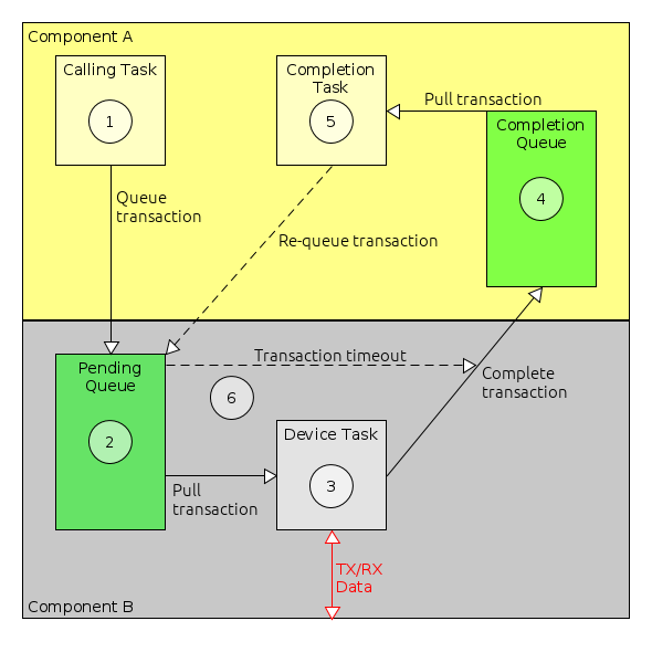
We can work through the process of receiving data asynchronously step-by-step. The steps are shown in Figure 8, and are as follows:
-
The component using PS, component A, initialises a transaction, setting the transaction’s receive buffer and size. The transaction is also associated with task queue of the sporadic task which will be triggered when the transaction completes. This is usually called the receive task. Component A then calls the asynchronous PS receive operation on its container, e.g.
ComponentA_PS_receiveAsyncBus. Via the framework, this calls the service provider, component B, passing it the transaction. -
Component B is providing PS. When the function for the receive operation is called, unless there is receive data immediately available (this is not normally the case) component B places the transaction on a pending queue. This queue holds receive transactions whilst they are waiting for data to be received.
-
When data is received, for example data received over a serial connection, the task handling received data in component B will then attempt to pull a transaction off it’s pending queue and place the received data into that transaction’s receive buffer. It will then complete that transaction, setting the transaction’s completion status based on how successfully it managed to store the received data.
-
When the transaction is completed, the framework adds the transaction to the task queue which was associated with the transaction in step 1. This task queue is part of component A, and will trigger the execution of a sporadic task on component A.
-
When the sporadic completion task runs, component A will check the completion status of the transaction. If the status is
STATUS_SUCCESS, then the data in the receive buffer can be used. Once the data has been used, the transaction can be reset and re-submitted to the PS provider ready for it to receive more data. -
When passing a transaction to receive data asynchronously, it’s possible to also provide a timeout for that transaction. If provided, then if the transaction is not pulled off the queue before the timeout (as in step 3, above), then the transaction will be completed with
STATUS_TIMEOUT.
Sending asynchronously is very similar to receiving, as shown in Figure 9.
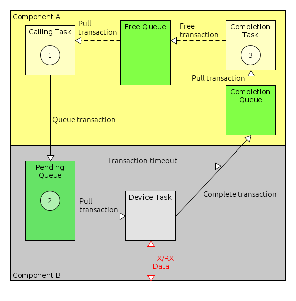
The main difference is where transactions spend most of their time queued. When component A is receiving, it will usually keep all receive transactions queued on the PS provider’s (component B’s) pending queue waiting for incoming data. For sending, component A will only pass a transaction to component B when is has some data to send. The transaction will be passed back to it when sending is complete. To allow component A to send more data before the first send operation has completed, it is common for it to have multiple available transactions and to keep these on a free queue.
-
Similar to receiving, when data is to be sent via PS, component A sets up a transaction with the buffer containing the data to send and its size. It also associates the transaction with the queue of a sporadic task which should be triggered when the send completes. The transaction is likely to have been pulled off a free queue, which holds transactions which are not currently being used for sending.
-
The handling by the service provider, component B, is identical to receiving. The incoming send transaction is placed on a pending queue. When component B is ready to send the data, it pulls the transaction off the pending queue, sends the data and then completes the transaction. As in the receive case, when the transaction is completed it is placed onto the associated task queue, triggering the transmit sporadic task.
-
When component A’s sporadic task executes, this indicates that the send has completed and the transaction may be used again. This can be done either immediately, or the transaction can be placed on the free queue for use in the future
As with the receive case, the transmit pending queue in component B typically supports timeouts.
7.11. Requesting a Connection Initialisation Stage
As described in Section 2.2.5.1, components may be initialised in two stages: one stage for internal initialisation and a second stage when connections with other components, such as via services, can be initialised. This second stage is optional, and can be requested by setting the connectionPhase attribute of the implementation tag to true.
<Implementation connectionPhase="true" />7.12. Adding Persistent Configuration
Components may have values that need to persist over reboots. These are stored inside a configuration structure which can be stored using the framework. The framework can also request that a component use a previously persisted configuration structure. A deployment can then deploy multiple configuration stores, which provide memory to store the data that needs to be persisted.
The configuration manager can then provide an interface to instruct the framework in the loading and storing of configuration data within a deployment. There is more information about using persistent configurations in Section 6.7.
7.12.1. Persistent Configuration in the Component
To allow a component to persist data:
-
In the
componentType.xmlfile, -
Set the configuration attribute of the Implementation tag to true
<Implementation configuration="true" /> -
Generate the component
-
Note if the component has already been generated:
-
A template version of the source file can be generated
-
This will include new functions for configuration
-
It will mention a configuration type with a signature similar to
*_config_t -
Such a type should be defined in the relevant
*_types.hheader file.
-
-
Use the
storeConfigstatic function to store the configuration type when changes are made to the configuration which should be persisted.-
Typical cases tend to be when parameters are set which are part of the configuration.
-
-
Other function will be provided for configuration, such as setConfig, which is called by the framework when loading a configuration into the component.
7.12.2. Using Persistent Configuration in a Deployment
For configuration to persist, there must be at least one ConfigStore component. When a deployment is generated, the ConfigStore component(s) will be mapped to configuration indices, starting from 1 (0 is the default configuration). A deployment should also have the ConfigurationManager component, which provides control over the loading and storing of configuration.
Examples of this are provided in the demonstration deployment for Linux (demo_linux) as well as the fully-featured examples for the Clyde Space platform (e.g. csl_primary).
8. Component tutorial: StoreAndForward
In this chapter, we will cover the steps involved in creating a new software component which is an example of a basic 'store-and-forward' messaging system. This will allow us to demonstrate a component which defines its own parameters, actions, events and exceptions, and that makes use of the Packet Service and tasking. We will call our new component StoreAndForward.
This example is inspired by the 'fitter' messages of the AMSAT-UK FUNcube satellite. This allows short SMS-style text message greetings to be uploaded from the ground-station which are subsequently broadcast to be picked up by schools as part of the satellite’s educational mission.
To follow this tutorial, we assume that you have set up your FSDK according to the installation instructions in Section 3 and that you have followed the Getting Started tutorial in Section 4. This tutorial goes through the process of creating the component step-by-step. The finished component source code is available in the gen1/OBSW/Source/legacy_tutorial2 directory.
For this tutorial, it will be assumed a component library project called saf_lib has been created, following the steps detailed in Section 7.1.1. The created component will then be placed in this project.
8.1. Defining the Model for the Component
The first step is to design the interface to our new StoreAndForward software component in terms of parameters, actions, events, exceptions, tasks and services. We can express this in an XML description which provides a 'model' for the component we are writing. This model can be used to generate the component container which interfaces the component into the component framework and allows the parameters, actions, exceptions and events to be accessed by other components and the ground. The codegen tool used to generate the container will also generate stubs for all of the component functions to get us started writing the component.
Our component will have the following features:
-
can store up to 32 messages, each of between 1 and 140 ASCII characters;
-
allows new messages to be uplinked from ground;
-
can be stopped and started;
-
when running will transmit each message in turn;
-
allows the number of times each message should be transmitted to be controlled;
-
allows the delay between each transmission to be controlled;
-
allows the next message to be transmitted to be controlled; and
-
generates events when stopping, starting and if an error occurs when sending a message.
To provide these features, we will use the following parameters, actions, exceptions and events.
8.1.1. Parameters
The table below briefly describes each of the parameters we need.
| Parameter Name | Type | Number of Rows | Description |
|---|---|---|---|
|
raw |
Up to 32 |
The messages to be sent. |
|
unsigned |
1 |
The gap between transmissions. |
|
unsigned |
1 |
The number of times to repeat a message before moving on. |
|
unsigned |
1 |
The number of messages being stored. |
|
unsigned |
1 |
The index of the next message to be transmitted. |
|
bitfield |
1 |
Indicates whether the component is started or stopped. |
Expressed as an XML fragment, it looks like this:
  <Parameters>
    <Parameter name="messages" readOnly="false">
      <Description>
        The messages to be sent, in the order they will be broadcast.
      </Description>
      <Vector maxRows="32">
        <Raw bytes="140"/>
      </Vector>
    </Parameter>
    <Parameter name="messagePeriod" readOnly="false">
      <Description>
        The gap between each message transmission as a multiplier of
        the base task period.
      </Description>
      <Value type="unsigned" bits="8"/>
    </Parameter>
    <Parameter name="messageRepeats" readOnly="false">
      <Description>
        The number of times to repeat each message before going to the next.
      </Description>
        <Value type="unsigned" bits="8"/>
    </Parameter>
    <Parameter name="messageCount" readOnly="true">
      <Description>
        The number of messages being stored.
      </Description>
        <Value type="unsigned" bits="6"/>
    </Parameter>
    <Parameter name="nextMessage" readOnly="false">
      <Description>
        The index of the next message to be transmitted.
      </Description>
        <Value type="unsigned" bits="6"/>
    </Parameter>
    <Parameter name="started" readOnly="true">
      <Description>
        Is the component currently started
      </Description>
      <Documentation><Text>
        0 = stopped
        1 = started
      </Text></Documentation>
      <Value type="bitfield" bits="1"/>
    </Parameter>
  </Parameters>
An important difference between Raw parameters and the other parameter types is that no adjustment for endianness is made for raw data whereas as other types will be translated to and from network-byte order when sent over the space-ground interface.
8.1.2. Actions
The table below briefly describes each of the actions we need.
| Name | Argument | Description |
|---|---|---|
|
Text of the message |
Add a message to the end of the store. |
|
None |
Clear all stored messages. |
|
None |
Start sending messages. |
|
None |
Stop sending messages. |
and in XML:
  <Actions>
    <Action name="appendMessage">
      <Description>
        Add a new message to the end of the list.
      </Description>
      <Argument name="text" minBytes="1" maxBytes="140" />
    </Action>
    <Action name="clearMessages">
      <Description>
        Clear all of the stored messages.
      </Description>
    </Action>
    <Action name="startSend">
      <Description>
        Start sending messages.
      </Description>
    </Action>
    <Action name="stopSend">
      <Description>
        Stop sending messages.
      </Description>
    </Action>
  </Actions>
8.1.3. Events
The table below briefly describes the events that we need. When logged by a deployment, these events will give a basic overview of what the StoreAndForward component has been doing.
| Name | Description |
|---|---|
|
Raised when sending starts |
|
Raised when sending stops |
|
Raised when a transmission fails |
In XML:
  <Events defaultBaseId="500">
    <Event name="sendStart" severity="info">
      <Description>
        The component has started sending messages.
      </Description>
      <Documentation><Text>
        The information field has the index of the next message to be
        transmitted.
      </Text></Documentation>
    </Event>
    <Event name="sendStop" severity="info">
      <Description>
        The component has stopped sending messages.
      </Description>
      <Documentation><Text>
        The information field shows the number of transmissions made.
      </Text></Documentation>
    </Event>
    <Event name="sendError" severity="error">
      <Description>
        An attempt to send a message failed.
      </Description>
      <Documentation><Text>
        The information field contains the message number and the error code.
      </Text></Documentation>
    </Event>
  </Events>
Note the defaultBaseId. This is used to make sure that each event in a deployed system has a unique identifier. Each component type should have a unique base ID and the actual identifier of an event is found by adding on the base ID. The base IDs need to be spaced far enough apart to ensure that there are no overlaps between the different components. We look at the base IDs documented in the file event_base.txt (in gen1/Documentation) and pick an unused block. You may need to keep track of how your own components use these IDs to make sure there are not clashes. You can check for clashes in a deployment when you export the spacecraft database to HTML as you did for the sample Linux deployment in Section 6.3.4.
8.1.3.1. Event Sources and Sinks
To allow the component to raise one of these events, we need to add an event source to the model. For this component, we only require a single source for the events. Below is an example of how to define an event source. It’s also possible for a component to listen for events. For this feature, a model needs an event sink to be defined.
In XML:
  <EventSources>
    <EventSource name="message">
      <Description>
        The event source for errors and message state changes.
      </Description>
    </EventSource>
  </EventSources>
8.1.4. Exceptions
We will have three exceptions:
| Name | Description |
|---|---|
|
Returned if we try to add a message with a length of 0 bytes |
|
Returned if we try to add a message that is more than 140 characters in length |
|
Returned if we try to store more than 32 messages |
In XML:
  <Exceptions defaultBaseId="33000">
    <Exception name="noMessage">
      <Description>
        A message to be added did not have any bytes.
      </Description>
    </Exception>
    <Exception name="messageTooLong">
      <Description>
        A message to be added was too long.
      </Description>
    </Exception>
    <Exception name="messageStoreFull">
      <Description>
        A message could not be added to the store because it is full.
      </Description>
    </Exception>
  </Exceptions>
In common with events, exceptions too have a defaultBaseId. We check for current allocations in the exception_base.txt file.
8.1.5. Tasks
We require a single task which will periodically send the next message. This is an example of a periodic task. The other permitted type is a sporadic task. An overview of tasking in the GenerationOne FSDK is provided in Section 2.2.5.3.
The XML is quite straightforward:
  <Tasks>
    <PeriodicTask name="main" defaultPeriod="5">
      <Description>
        The main execution task
      </Description>
    </PeriodicTask>
  </Tasks>
8.1.6. Services
We require the use of the packet service (PS) which allows us to send and receive chunks of data (packets) in a peer-to-peer way. For the StoreAndForward component, we will use PS for sending our messages. In the legacy_tutorial2 component library, there is another example component called SerialDemo which also receives over PS.
In XML:
  <Services>
    <Required>
      <Service name="message" type="io.PS">
        <Description>
          Uses the PS service to send a message.
        </Description>
      </Service>
    </Required>
  </Services>
We will call the new component type StoreAndForward and place it within a 'mission' directory in the saf_lib library that we should have created earlier (gen1/OBSW/Source/saf_lib). The component type can be easily created using the Codegen tool (refer back to Section 7 for a reminder on how this can be done). Since we want this component type to reside within a 'mission' directory, ensure to include mission within the component type’s dot notation path in the Codegen command. You also don’t need to worry about including any board configuration arguments since this component is platform independent. Once created, complete the componentType.xml file according to the component’s requirements.
The completed XML file should look like this:
<?xml version="1.0" encoding="UTF-8"?>
<ModelElement xmlns="http://www.brightascension.com/schemas/gen1/model"
    xmlns:xsi="http://www.w3.org/2001/XMLSchema-instance">
<ComponentType name="mission.StoreAndForward">
  <Description>
    StoreAndForward stores short SMS-style text messages uplinked from the ground station
    and later broadcasts them using the Packet Service.
  </Description>
  <!-- Exceptions (Status Codes) -->
  <Exceptions defaultBaseId="33000">
    <Exception name="noMessage">
      <Description>
        A message to be added did not have any bytes.
      </Description>
    </Exception>
    <Exception name="messageTooLong">
      <Description>
        A message to be added was too long.
      </Description>
    </Exception>
    <Exception name="messageStoreFull">
      <Description>
        A message could not be added to the store because it is full.
      </Description>
    </Exception>
  </Exceptions>
  <!-- Events -->
  <Events defaultBaseId="30">
    <Event name="sendStart" severity="info">
      <Description>
        The component has started sending messages. The information
        field has the index of the next message to be transmitted.
      </Description>
    </Event>
    <Event name="sendStop" severity="info">
      <Description>
        The component has stopped sending messages. The information
        field shows the number of transmissions made.
      </Description>
    </Event>
    <Event name="sendError" severity="error">
      <Description>
        An attempt to send a message failed. The information field
        contains the message number and the error code.
      </Description>
    </Event>
  </Events>
  <!-- Services -->
  <Services>
    <Required>
      <Service name="message" type="io.PS">
        <Description>
          Uses the PS service to send a message.
        </Description>
      </Service>
    </Required>
  </Services>
  <!-- Tasks -->
  <Tasks>
    <PeriodicTask name="main" defaultPeriod="5">
      <Description>
        The main execution task
      </Description>
    </PeriodicTask>
  </Tasks>
  <!-- Event Sources -->
  <EventSources>
    <EventSource name="message">
      <Description>
        The event source for errors and message state changes.
      </Description>
    </EventSource>
  </EventSources>
  <!-- Actions -->
  <Actions>
    <Action name="appendMessage">
      <Description>
        Add a new message to the end of the list.
      </Description>
      <Argument name="text" minBytes="1" maxBytes="140" />
    </Action>
    <Action name="clearMessages">
      <Description>
        Clear all of the stored messages.
      </Description>
    </Action>
    <Action name="startSend">
      <Description>
        Start sending messages.
      </Description>
    </Action>
    <Action name="stopSend">
      <Description>
        Stop sending messages.
      </Description>
    </Action>
  </Actions>
  <!-- Parameters -->
  <Parameters>
    <Parameter name="messages" readOnly="false">
      <Description>
        The messages to be sent, in the order they will be broadcast.
      </Description>
      <Vector maxRows="32">
        <Raw bytes="140"/>
      </Vector>
    </Parameter>
    <Parameter name="messagePeriod" readOnly="false">
      <Description>
        The gap between each message transmission as a multiplier of
        the base task period.
      </Description>
      <Value type="unsigned" bits="8"/>
    </Parameter>
    <Parameter name="messageRepeats" readOnly="false">
      <Description>
        The number of times to repeat each message before going to the next.
      </Description>
        <Value type="unsigned" bits="8"/>
    </Parameter>
    <Parameter name="messageCount" readOnly="true">
      <Description>
        The number of messages being stored.
      </Description>
        <Value type="unsigned" bits="6"/>
    </Parameter>
    <Parameter name="nextMessage" readOnly="false">
      <Description>
        The index of the next message to be transmitted.
      </Description>
        <Value type="unsigned" bits="6"/>
    </Parameter>
    <Parameter name="started" readOnly="true">
      <Description>
        Is the component currently started
      </Description>
      <Documentation><Text>
        0 = stopped
        1 = started
      </Text></Documentation>
      <Value type="bitfield" bits="1"/>
    </Parameter>
  </Parameters>
</ComponentType>
</ModelElement>
8.2. Generating the Container
Once the componentType.xml file is complete, we can then use it to generate all the boilerplate code for our new component type.
Use the Codegen tool to generate the new component type (refer to Section 7 for a reminder on how this can be done). Again, ensure to include mission within the dot notation path, and remember there is no need to include any board configuration arguments since it is platform independent.
The Codegen command will add the following files to your new component type’s inc and src directories.
| File | Description |
|---|---|
|
Package-visible definitions for the ActionSrc interface to the component. |
|
Private definitions for the ActionSrc interface to the component. |
|
Defines the Action IDs for the component. |
|
Package-visible definitions for the component container. |
|
Declarations for the StoreAndForward container. |
|
Defines the Event IDs for the component. |
|
Defines the Exception IDs for the component. |
|
Package-visible definitions for the ParamSrc interface to the component. |
|
Private definitions for the ParamSrc interface to the component. |
|
Defines the Parameter IDs for the component. |
|
Declarations for interacting with the PS services defined by the model. |
|
A header file created to allow for Cmock to generate a mock file. |
|
Defines the sizes of various parameters to help test against the maximum rows of parameters. |
|
Defines build-time configuration options for the StoreAndForward component type. |
|
Defines the type of a StoreAndForward component and its initialisation data type. |
|
Defines the public interface to the component. |
|
Implements the ActionSrc interface. |
|
Implements the Container. |
|
Implements the ParamSrc interface. |
|
Implements the PS interface. |
|
Main component code. |
Note that the suffixes _private and _package are indications of visibility. The suffix _package indicates an interface that should be visible to any part of the component. The suffix _private indicates an interface which is internal to a particular translation unit.
While there are quite a lot of files here, in practice most of them do not require user modification. The container generator splits things up into so many files to make it easy for you to re-generate one part of the container without affecting other parts. The only files we would ever need to modify to create a component are:
-
StoreAndForward_config.h -
StoreAndForward_types.h -
StoreAndForward.c
If we need to make changes which affect the other files, such as changing the component interface, then the best way to do it is to modify the component model XML file and regenerate the component using the Codegen tool.
8.3. Fleshing out the Component
We have now created a component, but it doesn’t actually do much yet. It will compile, and it could even be deployed, but we wouldn’t be able to access any of the component parameters or actions because there isn’t any component implementation code yet. We need to fill out the stubs that the code generator has created for us. We will be adding code to the function stubs in the StoreAndForward.c file. The code generator has created prototypes for all of these functions, with Doxygen documentation, in the StoreAndForward.h header file. To find out what a function stub should do, and what the function arguments are for, you can check this generated documentation. Type definitions, and any pre-processor defines we need, will be added to the StoreAndForward_types.h file.
8.3.1. Adding Component Variables
Each component instance can have variables associated with it which are accessible to all of the functions that make up the component. This is achieved by having a C structure, the component type, which is instantiated for each instance of the component. A pointer to this instance is then passed to all of the component functions. Effectively, the instance of the component type is the component instance.
The component type for the StoreAndForward component is defined in the StoreAndForward_types.h header file. The automatically-generated type for StoreAndForward is as follows:
/** The StoreAndForward component */
typedef struct
{
    /** Initialisation data */
    const StoreAndForward_Init_t *pt_Init;
    /** A protection lock to protect the StoreAndForward state */
    Task_ProtectionLock_t t_Lock;
    /* TODO: Add component variables here */
    /* The following variables are intended to help you keep track of the size
     * of variable-length parameters. You can easily use alternative schemes if
     * you want to. */
    /** The length, in rows, of the messages parameter */
    ui16_t u16_MessagesLength;
}
StoreAndForward_t;
To add variables to the component we add them in place of the comment (“TODO: Add component variables here”). The code generator will also pick up that there is a variable-length vector (the messages parameter) and generate a variable that can be used in the source to track the current length of the corresponding vector. This is optional and can be replaced.
Our StoreAndForward component needs component variables to store the data we have decided will be available as parameters:
-
all of the messages;
-
the period in between message transmissions;
-
the number of times a message transmission should be repeated;
-
the index of the next message to transmit;
-
the current state of message transmission (started or stopped);
-
the countdown for how many task calls should be called before the next send;
-
the countdown for how many times to send the current message before moving onto the next one;
-
the current message being transmitted.
These variables can be added as follows:
/** The StoreAndForward component */
typedef struct
{
    /** Initialisation data */
    const StoreAndForward_Init_t *pt_Init;
    /** A protection lock to protect the StoreAndForward state */
    Task_ProtectionLock_t t_Lock;
    /** Message data */
    char_t rrc_Messages[STOREANDFORWARD_MESSAGES_MAX_ROWS][STOREANDFORWARD_MESSAGES_ROW_SIZE];
    /** Number of invocations of task functions between each message */
    ui8_t u8_MessagePeriod;
    /** Number of times to send each message */
    ui8_t u8_MessageRepeats;
    /** Index of the next message to be transmitted */
    ui8_t u8_NextMessage;
    /** True if we should be sending messages */
    boolean_t b_Started;
    /** The length, in rows, of the messages parameter */
    ui16_t u16_MessagesLength;
}
StoreAndForward_t;
As well as the data storage for the parameters, the component needs to keep track of its current transmission state. We will add some more variables to do this when we start to implement the transmission algorithm.
For now, we should make sure that the component variables we have just added are properly initialised. The correct place to do this is in the StoreAndForward_localInit function, which is responsible for initialising the internal component state. For now we just initialise the component variables to constant values:
status_t StoreAndForward_localInit
(
    StoreAndForward_t *pt_StoreAndForward,
    const StoreAndForward_Init_t *pt_InitData
)
{
    status_t t_Status;          /* Current status */

    /*
     * Initialise the component structure
     */

    /* Set the initialisation data */
    pt_StoreAndForward->pt_Init = pt_InitData;

    /* Set initial state */
    pt_StoreAndForward->b_Started = FALSE;
    pt_StoreAndForward->u8_MessagePeriod = 1;
    pt_StoreAndForward->u8_MessageRepeats = 1;
    pt_StoreAndForward->u16_MessagesLength = 0;
    pt_StoreAndForward->u8_NextMessage = 0;

    /* Basic component initialisation was successful */
    t_Status = STATUS_SUCCESS;

    /* Only continue if initialisation so far was successful */
    if (t_Status == STATUS_SUCCESS)
    {
        /* Initialise the protection lock */
        t_Status = Task_ProtectionLock_init(
            &pt_StoreAndForward->t_Lock,
            STOREANDFORWARD_CONTAINER_TASKING_TYPE(pt_StoreAndForward));
    }

    return t_Status;
}
8.3.2. Parameter Accessors
The value of each parameter which we described can be obtained from the component using an accessor function. The accessor for reading the parameter value is always called getXXX where the 'XXX' is replaced with the parameter name. So, for example, the messagePeriod parameter has the accessor function getMessagePeriod. Most of the accessors are quite easy to implement: all they need to do is pass the parameter value back to the caller. To make sure that the state of the component variables are always consistent, we protect the component variables using a protection lock (just like a mutex, or binary semaphore). We enclose the code which accesses the component variables in special start and end statements which acquire and then release the protection lock. It is possible to specify a timeout to the protection lock handling statements. This makes sure that, even if the lock is being held for a really long time, the function will only wait for a predictable length of time. You can ask for an infinite wait (by specifying NULL) but we don’t recommend this as, in general, it is less safe. The status of the protection lock handling is reported in the specified status variable.
A complete parameter get accessor for the messagePeriod parameter is as follows:
status_t StoreAndForward_getMessagePeriod
(
StoreAndForward_t *pt_StoreAndForward,
ui8_t *pu8_Value
)
{
status_t t_Status; /* The current status */
TASK_PROTECTED_START(&pt_StoreAndForward->t_Lock, >_LockTimeout, t_Status)
{
*pu8_Value = pt_StoreAndForward->u8_MessagePeriod;
t_Status = STATUS_SUCCESS;
}
TASK_PROTECTED_END(&pt_StoreAndForward->t_Lock, >_LockTimeout, t_Status);
return t_Status;
}Parameters which are not read-only also have set accessors. These are equivalent to the get accessors we’ve just discussed. For example, the set accessor for the messagePeriod parameter is as follows:
status_t StoreAndForward_setMessagePeriod
(
StoreAndForward_t *pt_StoreAndForward,
ui8_t u8_Value
)
{
status_t t_Status; /* The current status */
TASK_PROTECTED_START(&pt_StoreAndForward->t_Lock, >_LockTimeout, t_Status)
{
pt_StoreAndForward->u8_MessagePeriod = u8_Value;
t_Status = STATUS_SUCCESS;
}
TASK_PROTECTED_END(&pt_StoreAndForward->t_Lock, >_LockTimeout, t_Status);
return t_Status;
}The accessors for the other simple, scalar, parameters (messageRepeats, messageCount, nextMessage and started) are all very simple, just like these ones.
Accessors become slightly more complicated when handling vector (multi-row) parameters, especially when those parameters can have a variable number of rows. In this case there are get and set accessors (unless the parameter is read-only, in which case there will be no set) but there is also a length accessor. This is called getXXXLength, where 'XXX' is the name of the parameter. So, for example, the messages parameter has three accessors: getMessages, setMessages and getMessagesLength:
-
the getMessages accessor gets the value of one or more rows of the parameter;
-
the setMessages accessor sets the value of one or more rows of the parameter, it may also change the number of rows available;
-
the getMessagesLength accessor gets the current number of parameter rows.
Accessors for multi-row parameters have additional arguments which specify the first and last row for the get or set. It is important that the accessor check these arguments to make sure they are valid. When the parameter has a variable number of rows, like the messages parameter, there is a Boolean argument specifying whether or not a resize has been requested. For a get, resize means that if the caller has specified a last row which is beyond the actual last row of the parameter, the accessor should change the request to place the last row within range. For a set, resize means that the caller wants to change the number of rows the parameter has so that the last valid row of the parameter after the set is the last row that was specified as an argument. This might make the parameter bigger, or it might make it smaller. It is also possible to append the list by setting the first row to be the row immediately following the current last row of the parameter.
The get accessor for the messages parameter is shown below. As you can see, the actual parameter access is very simple, most of the code is there to check the accessor arguments. Note that although the basis of the validation code is generated for you, the code can be altered to suit the requirements of the mission.
status_t StoreAndForward_getMessages
(
StoreAndForward_t *pt_StoreAndForward,
ui16_t u16_FirstRow,
ui16_t *pu16_LastRow,
boolean_t b_Resize,
ui8_t *pu8_Values
)
{
status_t t_Status; /* The current status */
ui16_t u16_CharsToCopy; /* The number of characters to copy */
TASK_PROTECTED_START(&pt_StoreAndForward->t_Lock, >_LockTimeout, t_Status)
{
/* Check the row arguments for validity */
if (u16_FirstRow > *pu16_LastRow)
{
/* Error: the row range must always be positive */
t_Status = STATUS_INVALID_PARAM;
}
else if (u16_FirstRow >= pt_StoreAndForward->u16_MessagesLength)
{
/* Error: first row is out of range */
t_Status = STATUS_INVALID_PARAM;
}
else if (*pu16_LastRow >= pt_StoreAndForward->u16_MessagesLength)
{
/* The last row is out of range, this is OK if we can resize */
if (b_Resize == FALSE)
{
/* Error: last row is out of range */
t_Status = STATUS_INVALID_PARAM;
}
else
{
/* Set the last row to the last valid row */
*pu16_LastRow = pt_StoreAndForward->u16_MessagesLength - 1;
t_Status = STATUS_SUCCESS;
}
}
else
{
/* The row range is valid */
t_Status = STATUS_SUCCESS;
}
/* Only continue if the row range is valid */
if (t_Status == STATUS_SUCCESS)
{
/* Determine how many message characters to copy */
u16_CharsToCopy = (*pu16_LastRow - u16_FirstRow) + 1;
u16_CharsToCopy *= STOREANDFORWARD_MESSAGES_ROW_SIZE;
/* Copy the messages */
memcpy(
pu8_Values,
pt_StoreAndForward->rrc_Messages[u16_FirstRow],
u16_CharsToCopy * sizeof(char_t));
}
}
TASK_PROTECTED_END(&pt_StoreAndForward->t_Lock, >_LockTimeout, t_Status);
return t_Status;
}This code uses the memcpy function; to make this available, add an include for string.h to the top of the file:
# include <string.h>As with the get accessor, most of the set accessor code is responsible for checking arguments.
status_t StoreAndForward_setMessages
(
StoreAndForward_t *pt_StoreAndForward,
ui16_t u16_FirstRow,
ui16_t u16_LastRow,
boolean_t b_Resize,
const ui8_t *pu8_Values
)
{
status_t t_Status; /* The current status */
ui16_t u16_CharsToCopy; /* The number of characters to copy */
TASK_PROTECTED_START(&pt_StoreAndForward->t_Lock, >_LockTimeout, t_Status)
{
/* Check the row arguments for errors */
if (u16_FirstRow > u16_LastRow)
{
/* Error: the row range must always be positive */
t_Status = STATUS_INVALID_PARAM;
}
else if (b_Resize == FALSE)
{
/* No resize requested, row range must be within current range */
if (u16_LastRow >= pt_StoreAndForward->u16_MessagesLength)
{
/* Error: the last row is out of range */
t_Status = STATUS_INVALID_PARAM;
}
else
{
/* Row range is OK */
t_Status = STATUS_SUCCESS;
}
}
else
{
/* Resize requested, row range must start within or just after
* the current range */
if (u16_FirstRow > pt_StoreAndForward->u16_MessagesLength)
{
/* Error: the first row is out of range */
t_Status = STATUS_INVALID_PARAM;
}
else if (u16_LastRow >= STOREANDFORWARD_MESSAGES_MAX_ROWS)
{
/* Error: the last row is out of range */
t_Status = STATUS_INVALID_PARAM;
}
else
{
/* Row range is OK */
t_Status = STATUS_SUCCESS;
}
}
/* Only do the copy if the row parameters were valid */
if (t_Status == STATUS_SUCCESS)
{
/* Determine how many message characters to copy */
u16_CharsToCopy = (u16_LastRow - u16_FirstRow) + 1;
u16_CharsToCopy *= STOREANDFORWARD_MESSAGES_ROW_SIZE;
/* Copy the messages */
memcpy(
&pt_StoreAndForward->rrc_Messages[u16_FirstRow][0],
pu8_Values,
u16_CharsToCopy * sizeof(char_t));
/* If a resize was requested, set the new last row */
if (b_Resize != FALSE)
{
pt_StoreAndForward->u16_MessagesLength = u16_LastRow + 1;
}
}
}
TASK_PROTECTED_END(&pt_StoreAndForward->t_Lock, >_LockTimeout, t_Status);
return t_Status;
}On the other hand, the accessor to get the parameter length is very simple. Note that this is automatically generated for you using the default length. If you changed this variable then you will need to update the corresponding function.
status_t StoreAndForward_getMessagesLength
(
StoreAndForward_t *pt_StoreAndForward,
ui16_t *pu16_Length
)
{
status_t t_Status; /* The current status */
TASK_PROTECTED_START(&pt_StoreAndForward->t_Lock, >_LockTimeout, t_Status)
{
/* Return the length of the messages parameter */
*pu16_Length = pt_StoreAndForward->u16_MessagesLength;
t_Status = STATUS_SUCCESS;
}
TASK_PROTECTED_END(&pt_StoreAndForward->t_Lock, >_LockTimeout, t_Status);
return t_Status;
}If you’ve been following along, and either writing or copying accessor code, you should now have code in all of the parameter accessor stubs. This means that all of the parameter handling for your component is done. The next sections will go on and fill out the rest of the component functionality, but it’s important to note that what you have now is a perfectly valid component, it just doesn’t do a lot. If you want, you could skip ahead to <<sec:sDeployingTheComponent} and add your current StoreAndForward component to a deployment and try it out. In fact, you could do that at the end of each of the following sections. Then come back and continue adding to your component. At this stage, you should find you can get, and set where appropriate, the values of your component parameters. You can try invoking the component actions, but these will return an error.
8.3.3. Initialisation Data
When you create a deployment with your component in it, you are effectively creating one (or more) instance(s) of your component. When you instantiate them you may want to be able to specify data which will configure that particular instance. In the GenerationOne FSDK we call this initialisation data. This is just like the information you would pass to an object constructor in Java or C++.
Initialisation data has a structure of its own. In a deployment you fill out this structure and the deployment gives it to the component manager, along with the component, so that the component manager knows how to initialise the instance. When you are writing a component, you can choose what initialisation you need by adding member variables to the initialisation data structure. The initialisation data structure type definition for the StoreAndForward component is in the StoreAndForward_types.h file and is called StoreAndForward_Init_t.
In our case, we want to allow the user to specify initial values for the messagePeriod and messageRepeat parameters. To do this we add two new member variables like this:
/** The StoreAndForward initialisation data */
typedef struct
{
    /** Initial value for the MessagePeriod parameter */
    ui8_t u8_InitialMessagePeriod;
    /** Initial value for the MessageRepeats parameter */
    ui8_t u8_InitialMessageRepeats;
}
StoreAndForward_Init_t;
Then we change the component variable initialisation code we wrote to use these two values:
status_t StoreAndForward_localInit
(
    StoreAndForward_t *pt_StoreAndForward,
    const StoreAndForward_Init_t *pt_InitData
)
{
    status_t t_Status;          /* Current status */

    /*
     * Initialise the component structure
     */

    /* Set the initialisation data */
    pt_StoreAndForward->pt_Init = pt_InitData;

    /* Set initial state */
    pt_StoreAndForward->b_Started = FALSE;
    pt_StoreAndForward->u8_MessagePeriod = pt_InitData->u8_InitialMessagePeriod;
    pt_StoreAndForward->u8_MessageRepeats = pt_InitData->u8_InitialMessageRepeats;
    pt_StoreAndForward->u16_MessagesLength = 0;
    pt_StoreAndForward->u8_NextMessage = 0;

    /* Basic component initialisation was successful */
    t_Status = STATUS_SUCCESS;

    /* Only continue if initialisation so far was successful */
    if (t_Status == STATUS_SUCCESS)
    {
        /* Initialise the protection lock */
        t_Status = Task_ProtectionLock_init(
            &pt_StoreAndForward->t_Lock,
            STOREANDFORWARD_CONTAINER_TASKING_TYPE(pt_StoreAndForward));
    }

    return t_Status;
}
You can see, in the line above where we use this new initialisation data, we actually keep a pointer to the initialisation data structure in the component itself. This means that we can get access to these initialisation values at any time.
It’s important to note that, by convention, the members of the initialisation data structure are treated as constant. This is enforced by the use of the const modifier. This allows the compiler to put this initialisation data into read-only memory, if it can, which is often a more efficient use of resources on embedded systems. Also by convention, initialisation data is expected to persist after component initialisation. This means that a component can just keep a pointer to the initialisation data and refer to it again later if it needs to; there is no need for a component to take a copy of the initialisation data.
8.3.4. Action Handlers
The StoreAndForward component has four actions: appendMessage, clearMessages, startSend and stopSend. You may have noticed, in the StoreAndForward.c file, that the code generator has generated function stubs for handlers for each of these four actions. For example, the startSend action handler is called StoreAndForward_startSend. Implementing the actions is a simple case of adding code to these handler stubs. The actions for clear messages and starting and stopping the sending of messages do not take any arguments, this makes them quite simple, so we’ll start with those.
The clearMessages action is the simplest: all we need to do is set the number of messages (the message length variable) to zero. As usual, we protect our access to the component variables with the protection lock:
status_t StoreAndForward_clearMessages
(
StoreAndForward_t *pt_StoreAndForward
)
{
status_t t_Status; /* The current status */
TASK_PROTECTED_START(&pt_StoreAndForward->t_Lock, >_LockTimeout, t_Status)
{
pt_StoreAndForward->u16_MessagesLength = 0;
t_Status = STATUS_SUCCESS;
}
TASK_PROTECTED_END(&pt_StoreAndForward->t_Lock, >_LockTimeout, t_Status);
return t_Status;
}Starting and stopping the sending of messages is pretty simple too. The main thing we need to do is to change the value of the Boolean started parameter appropriately:
status_t StoreAndForward_startSend
(
StoreAndForward_t *pt_StoreAndForward
)
{
status_t t_Status; /* The current status */
TASK_PROTECTED_START(&pt_StoreAndForward->t_Lock, >_LockTimeout, t_Status)
{
/* Only bother changing the state if it needs to be changed */
if (pt_StoreAndForward->b_Started == FALSE)
{
pt_StoreAndForward->b_Started = TRUE;
UTIL_LOG_INFO("Started forwarding messages");
}
/* Always succeeds */
t_Status = STATUS_SUCCESS;
}
TASK_PROTECTED_END(&pt_StoreAndForward->t_Lock, >_LockTimeout, t_Status);
return t_Status;
}The statement UTIL_LOG_INFO("Started forwarding messages") is just like a printf (the valid arguments and format specifiers are identical, except that it goes via the framework). There are three types of debug logging:
-
UTIL_LOG_INFO -
UTIL_LOG_DEBUG -
UTIL_LOG_ERROR
The reason for using these statements, rather than a printf, is three-fold.
-
Extra information, like the file and line number, get added to the displayed output automatically. This helps when trying to debug components without an interactive debugger.
-
You can easily control how much output you get from your deployment by changing the logging level. This is done by specifying a value for the
UTIL_LOG_LEVELdefine, which is usually done in the build configuration. If you specify a value of 3, you will get info, debug and error log output. A level of 2 will produce only debug and error log output; 1 will produce only error output; and 0 will produce no output at all. -
It is possible to redirect the output to somewhere other than stdout without modifying the code in your components. This can be done to direct logging output to a file, or even to transfer logging output across the TM/TC link.
The logging statement is contained within the logging system, which is part of the framework. The header is automatically included when the source is generated.
The code for the stopSend action handler is equivalent to the start handler, with the values for the started parameter modified and the logging text changed.
The action handler for the appendMessage action is a little different because it takes an argument: the message to append to the list of messages. We need to copy the message data into our component variable containing all of the messages, into the next free message slot. Before we do this, we must make sure that there is a free slot available, and that the message is a valid length.
When we copy the message in, we first make sure to zero out the message slot. This is so that, if the message is short, unused characters are guaranteed to be zero. When we send the message, we stop sending characters when we reach the first zero-valued byte. Note that basic error checking is automatically generated, however we replace the STATUS_INVALID_PARAM status that’s set with the component specific exceptions to make it more meaningful.
status_t StoreAndForward_appendMessage
(
StoreAndForward_t *pt_StoreAndForward,
const ui8_t *pu8_Text,
ui8_t u8_Length
)
{
status_t t_Status; /* The current status */
char_t* pc_Message; /* The destination for the message */
/* Check the length of the argument is valid */
if (u8_Length < STOREANDFORWARD_APPEND_MESSAGE_MIN_ARG_SIZE)
{
/* Error: invalid argument length */
t_Status = STOREANDFORWARD_STATUS_NO_MESSAGE;
}
else if (u8_Length > STOREANDFORWARD_APPEND_MESSAGE_MAX_ARG_SIZE)
{
/* Error: invalid argument length */
t_Status = STOREANDFORWARD_STATUS_MESSAGE_TOO_LONG;
}
else if (pt_StoreAndForward->u16_MessagesLength >=
STOREANDFORWARD_MESSAGES_MAX_ROWS)
{
t_Status = STOREANDFORWARD_STATUS_MESSAGE_STORE_FULL;
}
else
{
TASK_PROTECTED_START(
&pt_StoreAndForward->t_Lock, >_LockTimeout, t_Status)
{
/* Grab a pointer to the next message for readability */
pc_Message =
&pt_StoreAndForward->
rrc_Messages[pt_StoreAndForward->u16_MessagesLength][0];
/* Clear the current message entry */
memset(pc_Message, 0, STOREANDFORWARD_MESSAGES_ROW_SIZE);
/* Copy in the new message */
memcpy(pc_Message, pu8_Text, u8_Length * sizeof(char_t));
pt_StoreAndForward->u16_MessagesLength++;
t_Status = STATUS_SUCCESS;
}
TASK_PROTECTED_END(
&pt_StoreAndForward->t_Lock, >_LockTimeout, t_Status);
}
return t_Status;
}The StoreAndForward component is progressing well: we have completed all of the parameter accessors and all of the action handlers. However, the component still doesn’t do very much. To get the component to send messages, we need to implement the periodic task. That will be the final step.
Before we do that, we’ll add one other bit of functionality. We wanted the StoreAndForward component to raise events when it is started and stopped. That’s what we’ll do in the next section.
8.3.5. Raising Events
Events are system-wide notifications of significant things. Typically, events are logged, so that you can trace what has been happening, and they may also be forwarded to ground in real time. A lot of events are to signal that something has gone wrong, but in some cases we just want to log confirmation that an expected onboard operation has completed successfully.
In the case of the StoreAndForward component, we want to raise events to indicate when we start and stop sending messages. These are not errors, just a significant change in state. To do this we need to raise an event using the function that is generated in StoreAndForward_Container_package.h.
To use the function, we simply specify the event we want to raise and the information we want to associate with the event, if any. For our start and stop action handlers, we just want to raise the appropriate start or stop event. For the information field, it might be useful to specify the index of the next message we are (or were, for stop) going to send.
Raising the event is just one extra statement, like this:
status_t StoreAndForward_startSend
(
StoreAndForward_t *pt_StoreAndForward
)
{
status_t t_Status; /* The current status */
TASK_PROTECTED_START(&pt_StoreAndForward->t_Lock, >_LockTimeout, t_Status)
{
/* Only bother changing the state if it needs to be changed */
if (pt_StoreAndForward->b_Started == FALSE)
{
pt_StoreAndForward->b_Started = TRUE;
StoreAndForward_Container_raiseMessageEvent(
pt_StoreAndForward,
STOREANDFORWARD_EVENT_SEND_START,
pt_StoreAndForward->u8_NextMessage);
UTIL_LOG_INFO("Started forwarding messages");
}
/* Always succeeds */
t_Status = STATUS_SUCCESS;
}
TASK_PROTECTED_END(&pt_StoreAndForward->t_Lock, >_LockTimeout, t_Status);
return t_Status;
}The addition to the stopSend handler, to raise the STOREANDFORWARD_EVENT_SEND_STOP event, is equivalent.
8.3.6. Periodic Task Function
Most of the work that the StoreAndForward component does takes place in a separate task. The code written for the task defines what that task will do when run. However the task itself isn’t created by the component; this is done by a deployment that instantiates the component.
A periodic task function is called periodically, in the context of a task. The code is expected to execute, and then return. The next time the period expires, the function will be called again. A periodic task function does not contain a loop which waits for the period to expire, that is handled by the task itself.
The StoreAndForward task needs to:
-
only send anything if the
startedparameter is true; -
only actually send anything after there have been messagePeriod calls to the task function;
-
send the message specified by
nextMessagenext; -
make sure each message is sent
messageRepeatstimes before moving on to the next one; -
once we have got to the end of the messages in the list, start again at the beginning;
-
take account of the fact that the message list may be empty, which is the case before any messages have been added.
To do this we need to keep track of our state in between calls to the periodic task function. This means that we need some more component variables. We need to keep track of:
-
how many task function calls there are to go before we do the next send (this is the message period);
-
how many more times we must send the current message before we move on to the next one; and
-
what the current message is.
We add these component variables as follows:
/** The StoreAndForward */
typedef struct
{
    /** Initialisation data */
    const StoreAndForward_Init_t *pt_Init;
    /** A protection lock to protect the StoreAndForward state */
    Task_ProtectionLock_t t_Lock;
    /** Message data */
    char_t rrc_Messages[STOREANDFORWARD_MAX_MESSAGES][STOREANDFORWARD_MESSAGE_LENGTH];
    /** Number of invocations of task functions between each message */
    ui8_t u8_MessagePeriod;
    /** Number of times to send each message */
    ui8_t u8_MessageRepeats;
    /** Index of the next message to be transmitted */
    ui8_t u8_NextMessage;
    /** True if we should be sending messages */
    boolean_t b_Started;
    /** Number of task function invocations before we do the next send  */
    ui8_t u8_CountdownToSend;
    /** Number of times we must send this message before going to the next */
    ui8_t u8_CountdownToNextMessage;
    /** Message currently being transmitted or NULL if there isn't one */
    char_t *pc_CurrentMessage;
    /** The length, in rows, of the messages parameter */
    ui16_t u16_MessagesLength;
}
StoreAndForward_t;
We also need to initialise them in the component local initialisation function:
status_t StoreAndForward_localInit
(
    StoreAndForward_t *pt_StoreAndForward,
    const StoreAndForward_Init_t *pt_InitData
)
{
    status_t t_Status;          /* Current status */

    /*
     * Initialise the component structure
     */

    /* Set the initialisation data */
    pt_StoreAndForward->pt_Init = pt_InitData;

    /* Set initial state */
    pt_StoreAndForward->b_Started = FALSE;
    pt_StoreAndForward->u8_MessagePeriod = pt_InitData->u8_InitialMessagePeriod;
    pt_StoreAndForward->u8_MessageRepeats = pt_InitData->u8_InitialMessageRepeats;
    pt_StoreAndForward->u8_MessageLength = 0;
    pt_StoreAndForward->u8_NextMessage = 0;
    pt_StoreAndForward->u8_CountdownToSend = 0;
    pt_StoreAndForward->u8_CountdownToNextMessage = 0;
    pt_StoreAndForward->pc_CurrentMessage = NULL;

    /* Basic component initialisation was successful */
    t_Status = STATUS_SUCCESS;

    /* Only continue if initialisation so far was successful */
    if (t_Status == STATUS_SUCCESS)
    {
        /* Initialise the protection lock */
        t_Status = Task_ProtectionLock_init(
            &pt_StoreAndForward->t_Lock,
            STOREANDFORWARD_CONTAINER_TASKING_TYPE(pt_StoreAndForward));
    }

    return t_Status;
}
Now we are ready to use these variables to control the sending of messages. As we need to make sure that the state of the component variables is consistent, we protect the body of the task function with the protection lock.
Here is the task function code so far. We’ve added quite a lot of comments to try and describe what is going on:
void StoreAndForward_taskMain
(
StoreAndForward_t *pt_StoreAndForward
)
{
status_t t_Status; /* The current status */
TASK_PROTECTED_START(&pt_StoreAndForward->t_Lock, >_LockTimeout, t_Status)
{
/* Only run if we have been started */
if (pt_StoreAndForward->b_Started)
{
/* Check if it's time to transmit */
if (pt_StoreAndForward->u8_CountdownToSend > 0)
{
/* It's not, do some more counting down */
pt_StoreAndForward->u8_CountdownToSend--;
}
else
{
/* Time to make the next transmission.
* First reset the count down */
pt_StoreAndForward->u8_CountdownToSend =
pt_StoreAndForward->u8_MessagePeriod;
/* Should we send the current message again? */
if (pt_StoreAndForward->u8_CountdownToNextMessage == 0)
{
/* Time to move on to the next message, if there is one */
if (pt_StoreAndForward->u16_MessagesLength == 0)
{
/* There are no messages to send */
pt_StoreAndForward->pc_CurrentMessage = NULL;
}
else
{
/* Get the next message */
pt_StoreAndForward->pc_CurrentMessage =
&pt_StoreAndForward->rrc_Messages[
pt_StoreAndForward->u8_NextMessage][0];
/* Move the next message indicator, if it goes out of
* range, send it back to the start */
pt_StoreAndForward->u8_NextMessage++;
if (pt_StoreAndForward->u8_NextMessage >=
pt_StoreAndForward->u16_MessagesLength)
{
pt_StoreAndForward->u8_NextMessage = 0;
}
/* Set the repeat count as we're starting with a new
* message */
pt_StoreAndForward->u8_CountdownToNextMessage =
pt_StoreAndForward->u8_MessageRepeats;
}
}
/* Do we have a current message? */
if (pt_StoreAndForward->pc_CurrentMessage != NULL)
{
/* TODO: Send the message here */
/* We've sent the current message once */
pt_StoreAndForward->u8_CountdownToNextMessage--;
}
}
}
}
TASK_PROTECTED_END(&pt_StoreAndForward->t_Lock, >_LockTimeout, t_Status);
if (t_Status != STATUS_SUCCESS) {
UTIL_LOG_ERROR("Error %u while trying to send message", t_Status);
StoreAndForward_Container_raiseMessageEvent(
pt_StoreAndForward, STOREANDFORWARD_EVENT_SEND_ERROR, t_Status);
}
}This code does everything the component needs to do, except actually send the message! We’ll come back to that in a moment.
When this code first executes, the count down variables are zero, so the function will try and send a message. If there isn’t one, the current message pointer gets set to NULL and nothing gets sent. If there is one, we record the current message and the next message. We always set up the period count down so that we only actually do anything the right number of iterations.
If anything goes wrong during the task function, we will set t_Status to a value other than STATUS_SUCCESS and an event will get raised indicating the error.
Now to add the code that actually sends the message. To do this we are going to use the Packet Service, which is part of the framework, but is accessed via the container. The Packet Service allows us to send and receive chunks of data (packets) in a peer-to-peer way. The actual device or protocol used for packet sending and receiving is handled by the way that component is connected in the deployment. The code generator will create package-accessible functions based on the required services as defined in the component XML. For this component, a PS_package.h file has been generated containing function prototypes and a macro to help use the PS service in simple cases.
We will use the Packet Service function PS_send to send the message. We need to specify:
-
the message data;
-
the length of the message;
-
a timeout to use in case any part of the send takes a long time to complete.
The timeout for the PS send is configurable, but this can be configured at component type build time, rather than component instance deployment time. To permit this we add another define to the StoreAndForward_config.h file:
/*---------------------------------------------------------------------------*
 * Build configuration defines
 *---------------------------------------------------------------------------*/

#ifndef STOREANDFORWARD_CONFIG_LOCK_TIMEOUT
/** The timeout to use for lock operations, in microseconds. */
#define STOREANDFORWARD_CONFIG_LOCK_TIMEOUT                 500000
#endif

#ifndef STOREANDFORWARD_CONFIG_IO_TIMEOUT
/** The timeout to use for all I/O operations, in microseconds. */
#define STOREANDFORWARD_CONFIG_IO_TIMEOUT                   5000000
#endif
We then create a global constant variable at the top of the StoreAndForward.c file to hold the timeout value:
/*---------------------------------------------------------------------------*
 * Global variables
 *---------------------------------------------------------------------------*/

/** The lock access timeout */
static const ShortTime_t gt_LockTimeout = STOREANDFORWARD_CONFIG_LOCK_TIMEOUT;

/** The I/O access timeout */
static const ShortTime_t gt_IOTimeout = STOREANDFORWARD_CONFIG_IO_TIMEOUT;
Now we are ready to add some code to the task function for actually sending the message. We need to calculate the size of the message (we’ll use strnlen for that) and then we can do the send. Rather than show the code for the whole function again, we’ve just shown the most relevant bits.
void StoreAndForward_taskMain
(
StoreAndForward_t *pt_StoreAndForward
)
{
status_t t_Status; /* The current status */
IO_BufferSize_t t_Size; /* The size of the message buffer */
TASK_PROTECTED_START(&pt_StoreAndForward->t_Lock, >_LockTimeout, t_Status)
{
...
/* Do we have a current message? */
if (pt_StoreAndForward->pc_CurrentMessage != NULL)
{
/* There is a message to send, so send it.
* First work out the message size, then send it using PS */
t_Size = strnlen(
pt_StoreAndForward->pc_CurrentMessage,
STOREANDFORWARD_MESSAGES_ROW_SIZE);
t_Status = StoreAndForward_PS_sendMessage(
pt_StoreAndForward,
(ui8_t *)pt_StoreAndForward->pc_CurrentMessage,
t_Size,
>_IOTimeout);
/* We've sent the current message once */
pt_StoreAndForward->u8_CountdownToNextMessage--;
}
...
}
TASK_PROTECTED_END(&pt_StoreAndForward->t_Lock, >_LockTimeout, t_Status);
...
}Now the task function will actually send the message, and the code for the StoreAndForward component is complete.
8.4. Creating Unit Tests
The strict split between a component and its container means that there is a strong dividing line between the the component code and the code for the rest of the system, including component management. This makes the component much easier to unit test. GenerationOne FSDK unit tests use the Unity unit testing framework together with the CMock library for creating mocks for other components and elements of the framework. The Unity and CMock documentation provide an excellent guide to writing unit tests with those libraries and we don’t intend to repeat that information here. Instead, we will build the StoreAndForward unit test in a way that illustrates how we usually use Unity and CMock in testing components developed using the FSDK. Note that a basis for unit tests can be generated through the code-generation tool.
To create unit tests for your new component, start by regenerating it again using the Codegen tool, but this time including the optional unit test flag, -u:
$ codegen componenttype generate <name-of-library> -n
  path.to.component.<name-of-component> -u
This should generate a test for StoreAndForward and place it within gen1/OBSW/Source/saf_lib/test/src/mission/ StoreAndForward. The generated test contains the basics of what would be needed for a complete unit test. It also contains an example test that shows what should be tested. If a component has a configuration associated with it, then additional tests are generated to spell out what should be done for testing the configuration. CMock can be used to mock external calls, and the generated unit test file will automatically mock the component’s container, as you’ll see is the next section.
8.4.1. Mocking the Container and the Packet Service
The generated unit test will automatically include the headers that ask CMock to produce a mock of various files. This is done by specifying the file, but with “Mock” in front of it. The build system will pick this up and request that CMock generate a mock.
#include "unity.h"
#include "mission/StoreAndForward/StoreAndForward.h"
#include "mission/StoreAndForward/StoreAndForward_config.h"
#include "mission/StoreAndForward/MockStoreAndForward_Container.h"
#include "mission/StoreAndForward/MockStoreAndForward_Container_package.h"
#include "mission/StoreAndForward/MockStoreAndForward_PS.h"
#include "mission/StoreAndForward/MockStoreAndForward_PS_package.h"
#include "util/Util_Log.h"

#include <string.h>
For this test, we’ll also include string.h to allow us to compare strings in the test.
8.4.2. Generated Global Variables
After the included headers, you should find that some global variables have been generated for you. These set up a container and get a global pointer to the component from this container. As you can see below, a TODO is set up to remind you to set up your component with the initialisation data that you want to test with. The global variable gpt_StoreAndForward will be what is used throughout the tests.
/** The initialisation data for the component */
static StoreAndForward_Init_t gt_InitData =
{
/* TODO: Set initial values for initialisation data */
};
/** The initialisation data for the container */
static StoreAndForward_Container_Init_t gt_ContainerInitData =
{
.t_TaskingType = TASK_TYPE_RTOS,
.pt_StoreAndForwardInit = >_InitData,
};
/** The container object */
static StoreAndForward_Container_t gt_StoreAndForwardContainer =
{
.pt_Init = >_ContainerInitData
};
/** A pointer to the component created by the container */
static StoreAndForward_t *gpt_StoreAndForward =
STOREANDFORWARD_COMPONENT_FROM_CONTAINER(>_StoreAndForwardContainer);8.4.3. Helper Functions
The global variables are followed by another section titled “Helper functions” that is currently empty. It’s in this section that a helper function for testing the configuration would be generated, additionally it’s this section that we’d advise placing non-test functions in for readability.
8.4.4. Component Initialisation and Finalisation
Following on from the helper function section is the set up / tear down section. We initialise the component in the setUp function, which is called by Unity at the start of every test. The component is relatively simple so all we need to do is initialise the component and test that it passes.
void setUp(void)
{
status_t t_Status; /* The current status */
/* Test initialisation functions */
t_Status = StoreAndForward_localInit(gpt_StoreAndForward, >_InitData);
TEST_ASSERT_EQUAL_UINT(STATUS_SUCCESS, t_Status);
}Similarly, at the end of each test, Unity calls the tearDown function. Here we finalise the component.
void tearDown(void)
{
    status_t t_Status;

    /* Test finalisation functions */
    t_Status = StoreAndForward_localFini(gpt_StoreAndForward);
    TEST_ASSERT_EQUAL_UINT(STATUS_SUCCESS, t_Status);
}
8.4.5. The Tests
The final section generated is the section for the actual tests. You will see that some tests have been generated for the component’s actions. Tests should make sure that not only do the component’s functions execute successfully, but also that they catch error cases. The generated unit tests will test that invalid invocations are caught. They also generated “success” tests, which include TODO comments for changes that should be made to complete the test.
Setting these tests out in separate test functions helps make the Unity output easier to follow and see which particular tests passed and where the failures are.
If a generated component has a configuration, then 5 additional tests can be generated that will provide the types of tests that should be done for the configuration with TODOs added in to help inform you of what needs to be filled in and/or replaced.
The generated tests should compile but not all the tests will currently pass. We’ll address these tests as we implement tests.
8.4.5.1. Test Set-Up
Before creating the tests, we’ll set up the data that we want to test with. At the top of the global variables add the following code:
/*---------------------------------------------------------------------------*
 * Global variables
 *---------------------------------------------------------------------------*/

#define TEST_INITIAL_MESSAGE_PERIOD 2
#define TEST_INITIAL_MESSAGE_REPEATS 3

static string_t gz_FirstMessage = "First test message";
static string_t gz_SecondMessage = "Second test message";

static char_t grrc_TestMessages[2][140] =
{
    {
        "First test message"
    },
    {
        "Second test message"
    }
};

static char_t grrc_MessageBuffer[2][140];

Then append the initialisation data like so:
/** The initialisation data for the component */
static StoreAndForward_Init_t gt_InitData =
{
    .u8_InitialMessagePeriod = TEST_INITIAL_MESSAGE_PERIOD,
    .u8_InitialMessageRepeats = TEST_INITIAL_MESSAGE_REPEATS,
};
We can now use these variables for testing the component.
8.4.5.2. Testing Actions and Parameters
Simple tests of actions and parameters consist of calling the action handler or parameter accessor functions and checking the results. For example, testing the appendMessage action handler can be done by calling appendMessage to try and append a new message, and then checking the state of the messages parameter using the getMessages accessor.
Update the generated `test_appendMessageSuccessful test with the following;`
void test_appendMessageSuccessful(void)
{
    status_t t_Status;
    char_t rc_Message[STOREANDFORWARD_MESSAGES_ROW_SIZE];
    ui8_t u8_MessageCount;
    ui16_t u16_LastRow = 0;

    t_Status = StoreAndForward_appendMessage(
        gpt_StoreAndForward, (ui8_t*)gz_FirstMessage, strlen(gz_FirstMessage));
    TEST_ASSERT_EQUAL(STATUS_SUCCESS, t_Status);

    t_Status = StoreAndForward_getMessageCount(
        gpt_StoreAndForward, &u8_MessageCount);
    TEST_ASSERT_EQUAL(STATUS_SUCCESS, t_Status);
    TEST_ASSERT_EQUAL(1, u8_MessageCount);

    t_Status = StoreAndForward_getMessages(
        gpt_StoreAndForward, 0, &u16_LastRow, FALSE, (ui8_t*)rc_Message);
    TEST_ASSERT_EQUAL(STATUS_SUCCESS, t_Status);
    TEST_ASSERT_EQUAL(
        0,
        strncmp(gz_FirstMessage, rc_Message, STOREANDFORWARD_MESSAGES_ROW_SIZE));
}
This tests that the append message action can invoke successfully and operates as expected.
The generated unit test also checks that it can handle invalid arguments being provided. These currently fail because the generated code expects STATUS_INVALID_PARAM to be returned. However, we’ve created component specific exceptions for these.
-
If you change the expected return status in
test_AppendMessageFailureLengthTooSmallto expectSTOREANDFORWARD_STATUS_NO_MESSAGEand similarly changetest_AppendMessageFailureLengthTooLargeto expectSTOREANDFORWARD_STATUS_MESSAGE_TOO_LONGand then rerun the tests, those should now pass.
/** Test failure invoking the appendMessage action
 * due the argument length being too small */
void test_AppendMessageFailureLengthTooSmall(void)
{
    status_t t_Status;              /* The current status */
    ui8_t ru8_Text[STOREANDFORWARD_APPEND_MESSAGE_MIN_ARG_SIZE - 1];

    /* Call with the length being too small */
    t_Status = StoreAndForward_appendMessage(
        gpt_StoreAndForward,
        &ru8_Text[0],
        STOREANDFORWARD_APPEND_MESSAGE_MIN_ARG_SIZE - 1);
    TEST_ASSERT_EQUAL_UINT(STOREANDFORWARD_STATUS_NO_MESSAGE, t_Status);
}

/** Test failure invoking the appendMessage action
 * due the argument length being too large */
void test_AppendMessageFailureLengthTooLarge(void)
{
    status_t t_Status;              /* The current status */
    ui8_t ru8_Text[STOREANDFORWARD_APPEND_MESSAGE_MAX_ARG_SIZE + 1];

    /* Call with the length being too large */
    t_Status = StoreAndForward_appendMessage(
        gpt_StoreAndForward,
        &ru8_Text[0],
        STOREANDFORWARD_APPEND_MESSAGE_MAX_ARG_SIZE + 1);
    TEST_ASSERT_EQUAL_UINT(STOREANDFORWARD_STATUS_MESSAGE_TOO_LONG, t_Status);
}-
The next test that we’ll add will check that the append action correctly handles the case where the list of messages to be sent is full.
void test_appendMessageStoreFull(void)
{
    status_t t_Status;
    ui8_t u8_i;

    for(u8_i = 0; u8_i < STOREANDFORWARD_MESSAGES_MAX_ROWS; u8_i++)
    {
        t_Status = StoreAndForward_appendMessage(
            gpt_StoreAndForward,
            (ui8_t*)gz_FirstMessage,
            strlen(gz_FirstMessage));
        TEST_ASSERT_EQUAL(STATUS_SUCCESS, t_Status);
    }

    t_Status = StoreAndForward_appendMessage(
        gpt_StoreAndForward,
        (ui8_t*)gz_FirstMessage,
        strlen(gz_FirstMessage));
    TEST_ASSERT_EQUAL(STOREANDFORWARD_STATUS_MESSAGE_STORE_FULL, t_Status);
}
The generated unit tests for startSend currently fails. This is because the startSend and stopSend action handlers expect an event to be dispatched when they are successfully invoked.
The generated test for stopSend currently passes, as no send has started and so calling it does nothing.
-
Because the stopSend action expects there to be a send in progress, we will combine the generated unit tests into a single test.
-
We will then add the expected calls to raise their respective events.
void test_startAndStopSend(void)
{
    status_t t_Status;
    boolean_t b_IsStarted;
    Event_t t_ExpectedStartEvent =
    {
            .u16_ID = STOREANDFORWARD_EVENT_SEND_START,
            .u32_Information = 0
    };

    Event_t t_ExpectedStopEvent =
    {
            .u16_ID = STOREANDFORWARD_EVENT_SEND_STOP,
            .u32_Information = 0
    };

    StoreAndForward_Container_raiseMessageEvent_Expect(
        gpt_StoreAndForward,
        t_ExpectedStartEvent.u16_ID,
        t_ExpectedStartEvent.u32_Information);
    t_Status = StoreAndForward_startSend(gpt_StoreAndForward);
    TEST_ASSERT_EQUAL(STATUS_SUCCESS, t_Status);

    t_Status = StoreAndForward_getStarted(gpt_StoreAndForward, &b_IsStarted);
    TEST_ASSERT_EQUAL(STATUS_SUCCESS, t_Status);
    TEST_ASSERT_EQUAL(TRUE, b_IsStarted);

    StoreAndForward_Container_raiseMessageEvent_Expect(
        gpt_StoreAndForward,
        t_ExpectedStopEvent.u16_ID,
        t_ExpectedStopEvent.u32_Information);
    t_Status = StoreAndForward_stopSend(gpt_StoreAndForward);
    TEST_ASSERT_EQUAL(STATUS_SUCCESS, t_Status);

    t_Status = StoreAndForward_getStarted(gpt_StoreAndForward, &b_IsStarted);
    TEST_ASSERT_EQUAL(STATUS_SUCCESS, t_Status);
    TEST_ASSERT_EQUAL(FALSE, b_IsStarted);
}-
Next we want to test that we can actually set what messages there are to be sent.
-
To help reduce the amount of code that we need to rewrite, we’re going to create a helper function that will try to successfully set the messages to the globals that we declared earlier.
/*---------------------------------------------------------------------------*
 * Helper functions
 *---------------------------------------------------------------------------*/

/** Helper function to set the message successfully */
static status_t setMessage(void)
{
    status_t t_Status;

    t_Status = StoreAndForward_setMessages(
        gpt_StoreAndForward, 0, 1, TRUE, (ui8_t*)grrc_TestMessages);

    return t_Status;
}
The first test on set messages we’ll do is to test that it runs successfully. After that, we’ll test that it can handle an invalid parameter and then finally we’ll test that we can get back the messages that we set.
void test_setMessagesSuccessful(void)
{
    status_t t_Status;
    ui8_t u8_MessageCount;

    t_Status = setMessage();
    TEST_ASSERT_EQUAL(STATUS_SUCCESS, t_Status);

    t_Status = StoreAndForward_getMessageCount(
        gpt_StoreAndForward, &u8_MessageCount);
    TEST_ASSERT_EQUAL(STATUS_SUCCESS, t_Status);
    TEST_ASSERT_EQUAL(2, u8_MessageCount);
}

void test_setMessagesInvalidParam(void)
{
    status_t t_Status;

    t_Status = StoreAndForward_setMessages(
        gpt_StoreAndForward, 2, 3, FALSE, (ui8_t*)grrc_TestMessages);
    TEST_ASSERT_EQUAL(STATUS_INVALID_PARAM, t_Status);
    t_Status = StoreAndForward_setMessages(
        gpt_StoreAndForward, 3, 4, TRUE, (ui8_t*)grrc_TestMessages);
    TEST_ASSERT_EQUAL(STATUS_INVALID_PARAM, t_Status);
}

void test_getMessagesSuccessful(void)
{
    status_t t_Status;
    ui16_t u16_LastRow = 1;

    /* Set the message successfully again so that we can try to get the
     * messages back */
    t_Status = setMessage();

    t_Status = StoreAndForward_getMessages(
        gpt_StoreAndForward,
        0,
        &u16_LastRow,
        FALSE,
        (ui8_t*)grrc_MessageBuffer);
    TEST_ASSERT_EQUAL(STATUS_SUCCESS, t_Status);

    TEST_ASSERT_EQUAL(0, strcmp(grrc_MessageBuffer[0], grrc_TestMessages[0]));
    TEST_ASSERT_EQUAL(0, strcmp(grrc_MessageBuffer[1], grrc_TestMessages[1]));
}
8.4.5.3. Testing Task Functions
There is no need to actually create a periodic task in order to test the StoreAndForward task function. Using an actual task would make the code quite difficult to unit test; instead, we simply call the task function from the test which gives us complete control over when and how it is executed.
As the task function is called, we indicate to Unity when we expect the Packet Service to be called for the sending of a message, and exactly which message we expect to be sent.
In this test we add two messages and check that they are sent as we expect.
void test_taskFunction(void)
{
    status_t t_Status;
    ShortTime_t t_Timeout  = STOREANDFORWARD_CONFIG_IO_TIMEOUT;

    t_Status = StoreAndForward_appendMessage(
        gpt_StoreAndForward, (ui8_t*)gz_FirstMessage, strlen(gz_FirstMessage));
    TEST_ASSERT_EQUAL(STATUS_SUCCESS, t_Status);

    t_Status = StoreAndForward_appendMessage(
        gpt_StoreAndForward, (ui8_t*)gz_SecondMessage, strlen(gz_SecondMessage));
    TEST_ASSERT_EQUAL(STATUS_SUCCESS, t_Status);

    // Ignore the raised event
    StoreAndForward_Container_raiseMessageEvent_Ignore();
    t_Status = StoreAndForward_startSend(gpt_StoreAndForward);
    TEST_ASSERT_EQUAL(STATUS_SUCCESS, t_Status);


    /* First Message */
    StoreAndForward_PS_sendSyncMessage_ExpectWithArrayAndReturn(
        gpt_StoreAndForward,
        1,
        (IO_Buffer_t*)gz_FirstMessage,
        strlen(gz_FirstMessage),
        strlen(gz_FirstMessage),
        &t_Timeout,
        1,
        STATUS_SUCCESS);
    StoreAndForward_taskMain(gpt_StoreAndForward);

    StoreAndForward_taskMain(gpt_StoreAndForward);
    StoreAndForward_taskMain(gpt_StoreAndForward);

    /* Second Message */
    StoreAndForward_PS_sendSyncMessage_ExpectWithArrayAndReturn(
        gpt_StoreAndForward,
        1,
        (IO_Buffer_t*)gz_SecondMessage,
        strlen(gz_SecondMessage),
        strlen(gz_SecondMessage),
        &t_Timeout,
        1,
        STATUS_SUCCESS);
    StoreAndForward_taskMain(gpt_StoreAndForward);

    StoreAndForward_taskMain(gpt_StoreAndForward);
    StoreAndForward_taskMain(gpt_StoreAndForward);

    StoreAndForward_PS_sendSyncMessage_ExpectWithArrayAndReturn(
        gpt_StoreAndForward,
        1,
        (IO_Buffer_t*)gz_SecondMessage,
        strlen(gz_SecondMessage),
        strlen(gz_SecondMessage),
        &t_Timeout,
        1,
        STATUS_SUCCESS);
    StoreAndForward_taskMain(gpt_StoreAndForward);

    /* Return to first message */
    StoreAndForward_taskMain(gpt_StoreAndForward);
    StoreAndForward_taskMain(gpt_StoreAndForward);
    StoreAndForward_PS_sendSyncMessage_ExpectWithArrayAndReturn(
        gpt_StoreAndForward,
        1,
        (IO_Buffer_t*)gz_FirstMessage,
        strlen(gz_FirstMessage),
        strlen(gz_FirstMessage),
        &t_Timeout,
        1,
        STATUS_SUCCESS);
    StoreAndForward_taskMain(gpt_StoreAndForward);
}
8.4.6. Running the Tests
The unit tests should be built when you do a build on the library with the StoreAndForward component and test code in. You can try the unit tests we’ve written simply by building saf_lib for Linux and executing the testStoreAndForward binary that is produced in the saf_lib/bin directory. This should produce the following output from Unity:
test/src/mission/StoreAndForward/test_StoreAndForward.c:118:
	test_AppendMessageFailureLengthTooSmall:PASS
test/src/mission/StoreAndForward/test_StoreAndForward.c:133:
	test_AppendMessageFailureLengthTooLarge:PASS
test/src/mission/StoreAndForward/test_StoreAndForward.c:147:
	test_AppendMessageSuccessful:PASS
test/src/mission/StoreAndForward/test_StoreAndForward.c:171:
	test_appendMessageStoreFull:PASS
test/src/mission/StoreAndForward/test_StoreAndForward.c:193:
	test_ClearMessagesSuccessful:PASS
INF: src/mission/StoreAndForward/StoreAndForward.c(309):
	Started forwarding messages
INF: src/mission/StoreAndForward/StoreAndForward.c(341):
	Stopped forwarding messages
test/src/mission/StoreAndForward/test_StoreAndForward.c:204:
	test_startAndStopSend:PASS
test/src/mission/StoreAndForward/test_StoreAndForward.c:243:
	test_setMessagesSuccessful:PASS
test/src/mission/StoreAndForward/test_StoreAndForward.c:257:
	test_setMessagesInvalidParam:PASS
test/src/mission/StoreAndForward/test_StoreAndForward.c:269:
	test_getMessagesSuccessful:PASS
INF: src/mission/StoreAndForward/StoreAndForward.c(309):
	Started forwarding messages
test/src/mission/StoreAndForward/test_StoreAndForward.c:290:
	test_taskFunction:PASS

-----------------------
10 Tests 0 Failures 0 Ignored
OK
Additionally, some debug output can be produced from the component itself when it is started and stopped by the tests (from the UTIL_LOG_INFO statements).
8.5. Deploying the Component
Now that we have developed, and unit tested, our StoreAndForward component, we can add it to a deployment and use it. To do this, we suggest that you follow a similar strategy as tutorial 1 and take a copy of the demo_linux sample deployment and use that. There is a provided deployment that includes StoreAndForward available in the gen1/OBSW/Source/legacy_tutorial3 directory. If you don’t want to do your own deployment yet, then you can just use legacy_tutorial3; alternatively, you can try doing the deployment yourself and checking your results against the solution we have provided.
The instructions here assume that your StoreAndForward component is in the saf_lib library. If you want to use the component source code we have provided, you will need to copy the sources files from legacy_tutorial2/inc and legacy_tutorial2/src to saf_lib/inc and saf_lib/src (respectively) making sure that you maintain the directory structure (e.g. inc/mission/StoreAndForward).
You will also need to make sure the saf_lib project is included in the DEPEND_DIR list in the project.mk config file as well as in the project’s 'Paths and Symbols' so that the Codegen tool can resolve the types.
8.5.1. Getting Set Up
The first step to creating a new deployment is to generate the basic file structure it requires using the Codegen tool (refer back to Section 6 for a reminder on how this can be done). Use the Codegen tool to create a new deployment named saf_test.
The next step is to update the deployment.xml file to describe the component instances and connections you wish to have in your deployment. The quickest and easiest way to do this is to copy an existing deployment which already has a similar structure to what you want, then modify it to suit your needs. In this case we suggest you base your new deployment off of the existing demo_linux deployment. Don’t worry about adding any new component instances to it yet, we will do that in the following section.
The same approach can then be used to update the config and make files, ensuring that TARGET, VALID_CONFIGS, and DEPEND_DIRS are set appropriately for your new deployment:
# Root target name
TARGET := saf_test

# Target type (bin or lib)
TARGET_TYPE := bin

# List of valid build configurations for this project (empty means all)
# If this is non-empty and DEFAULT_CONFIG is not specified, the first
# configuration from this list is used as the default configuration
VALID_CONFIGS :=

# Dependencies (library directories)
DEPEND_DIRS := ../app ../framework ../saf_lib
TEST_DEPEND_DIRS :=
Notice we have set TARGET := saf_test, and added saf_lib to DEPEND_DIRS because we are going to add an instance of StoreAndForward from the saf_lib library to the deployment.
Now generate the deployment, referring to Section 6.3 if you’re not sure how to do this. After that, copy across the src/init directory from demo_linux so that the init data is filled out. You can actually check that your deployment builds at this point. You should get an executable called saf_test in the bin directory which you can execute and use exactly as you did the demo_linux deployment (see Section 4).
8.5.2. Component Instantiation
The first thing we need to do is to create an instance of our StoreAndForward component in our deployment. More specifically, what we actually do is create an instance of the StoreAndForward container, the container then creates and manages the component instance.
A component instance is a set of data declarations, some of which are initialised with data. There is no actual code. Because of this, these component instantiation files are quite repetitive. It is usually a good idea to copy files from a similar component instance and modify them.
As with tutorial 1, to add the component instance, you first need to import the mission.StoreAndForward component type in the deployment.xml <Import> section.
The component can then be instantiated by adding a <Component> element at the bottom of the deployment.xml <Deploy> section.
As can be found by checking the library documentation, StoreAndForward uses a service and also contains a periodic task. These will need to be set up within the <Component> element you have just created. First to set up are the connections so create a connection → service block and add the component and service to use for sending.
The Packet Utilisation Standard specifies a standard TM/TC protocol, together with a standard set of TM/TC services. The GenerationOne FSDK has an implementation for the PUS protocol and some of the key services. The demonstration deployments, and TMTC Lab, all use PUS. In addition to the specified services, PUS permits the implementer to add additional services of their own. We have done this to transfer parameter data when you carry out a 'Get'. The TMTC Lab software understands one more custom service, which is very simple telemetry packets which contain debug messages. These telemetry packets are identified by service ID 129 and sub-service ID 1. We will use these to transfer our messages from StoreAndForward.
The main PUS protocol handler is called PUSCore. In the demo_linux deployment, which we will use as a base, it specifies channels for event forwarding, function management ('Get', 'Set' and 'Invoke' requests) and a special channel for return data from functions. We will need to add one more channel for debug messages.
The service name for StoreAndForward is 'message' and we want to use the 'dataPacket' service provided by PUSCore. Checking PUSCore in the framework library documentation shows that the component’s container can support up to 8 channels. In this deployment, channels 0 – 6 are being used by the other component connections just described and so we’ll use the next one along.
Next set up the task. The name is 'main' and we want the task to get called every second. We’ll also place it at a higher priority.
    <Component name="mission.StoreAndForward" type="mission.StoreAndForward">
      <Connections><Services>
        <Service name="message" component="comms.pus.PUSCore"
         service="dataPacket" channel="7"/>
        </Services></Connections>
      <Tasks>
        <PeriodicTask name="main" period="1.0" priority="3"/>
      </Tasks>
    </Component>
Now regenerate the deployment using the same approach as before.
We now need to update some of the init data related to our new component instance.
First we will update the initialisation data for PUSCore by adding in the new channel. Open src/init/comms/pus/PUSCore_Init.c and add the section below to the end of the grt_PUSCoreChannelInit[] array.
        /* D_PUSCORE_CHANNEL_DEBUG_MESSAGE */
        {
            .u8_Service = 129,
            .u8_MinSubservice = 1,
            .u8_MaxSubservice = 1,
            .u8_AckMask = 0,
            .b_IncludeSubservice = FALSE,
            .b_SingleAck = TRUE,
            .u8_AckStatusSize = 1
        },
The additional channel specification specifies that we would like a new channel which transfers service ID 129, and only sub-service ID 1. The AckMask, SingleAck and AckStatusSize are related to the acknowledgement of telecommands on the channel. As there are no telecommands on this channel, they are not relevant. The IncludeSubservice parameter specifies whether the data that is passed on the channel (both for receive and send) should have the sub-service ID as the first byte. As our subservice ID is fixed, and we want to be able to send our messages without adding a sub-service ID at the start, we specify FALSE here.
Next, let’s set the initialisation data for our StoreAndForward component to use this new channel. Open src/init/mission/StoreAndForward_Init.c and replace the TODO comment with the following code:
.u8_InitialMessagePeriod = 5,
.u8_InitialMessageRepeats = 1
This is all that is needed to initialise the StoreAndForward component.
8.5.3. Trying Out the Component
Execute the deployment, and run TMTC Lab, it should connect to your deployment. As with tutorial 1, the Spacecraft Database should be generated and then open that in TMTC Lab.
As a simple test, try appending a new message by invoking the appendMessage``StoreAndForward action specifying the message. We need to specify the message in hexadecimal, for example: 48656c6c6f2c20576f726c6421. Now you can start sending by invoking the startSend action.
In the packet monitor window, you should see (after the action invocation telecommands and their acknowledgements) an event, indicating that sending has started and, possibly after a delay, a debug message. Additionally, you should be able to see the debug message in the debug console. This is shown in Figure 10. You should now be able to try out the other features of StoreAndForward.

9. The TMTC Lab “Ground” Software
TMTC Lab is a desktop application that allows you to communicate with your spacecraft in test and development environments. Its purpose is to allow efficient interaction with the on-board software and to allow you to test the on-board software as it’s being developed. This chapter begins with a brief introduction on how to start using TMTC Lab with your spacecraft and goes on to describe the layout and functionality of TMTC Lab in more detail.
9.1. Interface
After opening TMTC Lab you will be presented with the main window, at the top is the toolbar (Figure 11) which allows you to perform the various fundamental operations of TMTC Lab, from left to right these are:
-
Manage deployments
-
Connect to the spacecraft
-
Disconnect from the spacecraft
-
Toggle housekeeping; this enables checks to incoming housekeeping packets
-
Toggle logging of housekeeping to a CSV file
-
Packet monitor
-
CFDP uplink
-
CFDP downlink
-
Transfers; displays the current state of transfers
-
Parameter table; lists current parameter values
-
Command Line Interface display; displays the scripting and command-line interface
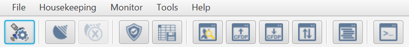
Below the toolbar, Lab is split vertically into the Mission Explorer to the left which displays various aspects of the mission in a tree structure including the currently open SCDB (see Section 9.1.1).
On the right-hand side is a 'dockable area'. This area will be blank to start with, you can customise the contents of this area using the various views available to TMTC Lab. This area can be configured for the particular workflow specific to the mission (see Section 9.1.4).
At the bottom, a log view displays various log sources including System, Events, and Debug (see Section 9.1.3).
9.1.1. Mission Explorer
One of the most intuitive methods of interacting with the spacecraft is through the Mission Explorer which will display a representation of a spacecraft database (SCDB), shown in Figure 12.
On first opening Lab, the Mission Explorer displays Sessions, Layouts, and Housekeeping. However, to view component groups and component instances present in a deployment, a deployment (SCDB) must be opened. This is explained in more detail in Section 9.2.2, however, for the moment an SCDB can be opened by clicking File → Manage deployments. Either add or select an existing target and click Select Deployment to choose an SCDB for the currently selected target.
Once an SCDB is open, the Mission Explorer tree view provides a list of all the component groups and component instances present in the deployment. Component groups allow components with similar functions to be grouped into easier to access and view areas. The groups are defined by the deployment. Components with parameters and/or actions can be expanded to reveal their list. Parameters and actions can be interacted with, e.g. fetching a parameter value, by first double-clicking on the component in the tree (this is explored more in Section 9.1.2).
At the top of the Mission Explorer there are 4 buttons:
-
Dock/undock documentation - docks/undocks the Mission Explorer documentation panel.
-
Show IDs - shows IDs for items in the SCDB.
-
Sort by ID - sorts nodes by ID.
To the right of these buttons is a search field that applies a fuzzy search to quickly lookup and jump to a particular node. This allows searching using the name of a component, for example, typing in 'dummy' brings up results for dummyParam8, dummyParam16, and dummyParam32, among others. Components can also be looked-up using their decimal or hexadecimal flight-ID. For example, typing the decimal ID of dummyParam32 prefixed with a hash, '#917504', will bring up dummyParam32 as a result. Alternatively, its ID in hex can be used by prefixing the number with '0x', for example, typing '0x000E0000' also brings up dummyParam32.
At the bottom of the Mission Explorer, interactive deployment documentation is displayed to allow you to view documentation without having to change between TMTC Lab and the HTML deployment documentation.
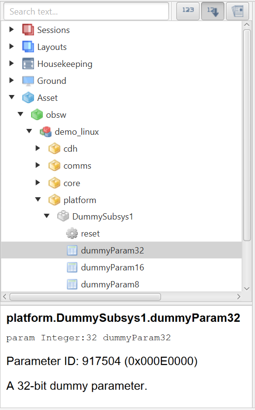
9.1.2. Interacting with Components
Interactions with parameters and actions are done via dialog windows representing different parameters/actions. For example, Figure 13 shows the dialog used to interact with dummyParam32, and Figure 14 shows the dialog used to invoke the OBT.reset action. To open a dialog, select the parameter/action of interest from the Mission Explorer.
Some options may also be disabled depending on what is available to that parameter. For example, some parameters only have a single row and so the ability to select a row range is disabled. Similarly, if the parameter is read-only, then the ability to uplink to set the parameter is disabled.
9.1.2.1. Parameter Get
Clicking the left-most down arrow on a parameter’s dialog will perform a parameter get request and return the requested data in the Data field, assuming that the command was issued successfully. Note that for vector and block parameters, the data is represented as zero-indexed rows. Getting a range of rows is inclusive of the row indices specified to get.
The dialog also indicates the state of the activity, e.g. parameter get. While a 'get' activity is in-progress, a blue spinner will appear next to the Data field. If the activity completes successfully, then a green tick is displayed. If the activity times-out, then a grey cross is displayed. If the activity fails, then a red cross is displayed. By hovering over the cross more information can be displayed about the exact error that occurred. This also applies to parameter sets, parameter downlinks, action invocations, etc.
The success of a command can be also checked using the Activity display ([ss:lab_secActivities]), with successful activities marked as 'completed'.
9.1.2.2. Parameter Set
To set the value of a parameter, first, enter the new value into the Data field, and then press the 'set' button (the left-most up arrow on the parameter’s dialog). As with other methods of interacting with the spacecraft, resize can be specified for both gets and sets (see Section 9.3.5.7).
9.1.2.3. Parameter Downlink
Get (and set) telecommands are limited to a single packet. For large data transfers, parameters will need to be downlinked using a bulk transfer protocol (such as PUS or LDT). To downlink the parameter, the right-most down arrow can be clicked. Clicking the icon will prompt you to choose a file in which the value of the downlinked parameter will be stored. The small dropdown arrow to the right of this enables a choice of whether to downlink to a single file, or multiple files, and a required protocol to use for the downlink.
To speed up workflow, right-clicking the downlink icon allows a default downlink file location to be chosen. Subsequent left-clicks of the downlink icon will then prepopulate the prompt with the default location.
9.1.2.4. Parameter Uplink
Similar to downlink, the uplink telecommand allows for more data to be sent to a parameter. To uplink a file, press the right-most up arrow to choose a file. The same behaviour of right-clicking to choose a default file also works for uplinking, as with downlinking.
9.1.2.5. Actions
Selecting an action from the Mission Explorer will bring up the options for interacting with the action, an example of which is shown in Figure 14. Depending on whether the action takes arguments, a text field for arguments may also be displayed. To invoke an action, simply click the forward arrow icon. This will result in a message in the spacecraft explorer stating 'Action invoked successfully', assuming the action was invoked successfully.
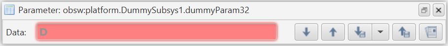
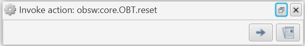
9.1.3. System/Debug/Event Console
The system/debug/event console provides three tabbed windows. The system tab gives an overview of the actions being taken by TMTCLab. The Debug tab displays debug log messages sent from a connected spacecraft. The event tab allows a more human-readable form (i.e. not packets) to view raised events.
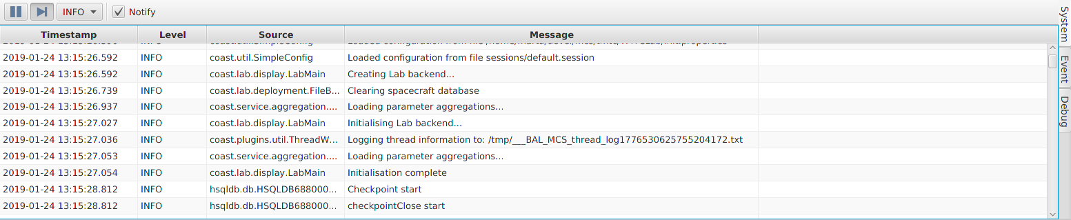
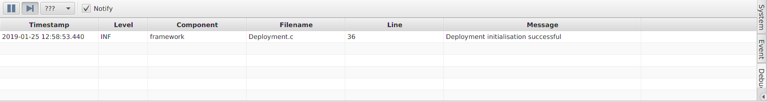
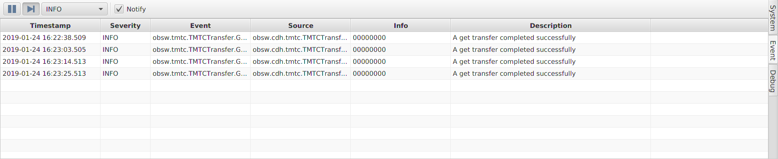
9.1.3.1. System
When starting TMTCLab, the System tab is the default (Figure 15). It shows TMTCLab’s processes as well as providing information such as failed error checks.
9.1.3.2. Event
When events are raised, a packet is sent which can be viewed in the Packet Monitor (see Section 9.3.1). However, the information stored in packets needs to be interpreted using the deployment’s spacecraft database documentation. An alternative is to view events through the Event tab on the System/Debug/Event Console (Figure 17). This provides more human-readable information about events that have been raised such as the name of the component source and the severity.
9.1.3.3. Debug
If a TMDebug component is set up (such as in the demo deployments), then standard output will be directed to the System/Debug/Event Console (Figure 16). Additional information will be provided for output from components that use the log utility (such as UTIL_LOG_DEBUG()).
This allows output to be viewable within the same window while working with a deployment, without having to swap back to the interface in which the deployment is running where the standard output is being directed.
9.1.4. Layouts
Layouts allow arrangements of windows, such as parameter dialogs, to be persisted and easily switched between. Existing layouts can be found under the Layouts section of the Mission Explorer. Right-clicking on the top-level layouts icon allows new layouts to be created.
Windows can be arranged in a layout by clicking and dragging. When a window is being moved, icons are displayed showing the locations the window can be docked to, as shown in Figure 18. The blue area shows the location the window will be docked when the mouse is released. In this way, layouts of windows can be built up.
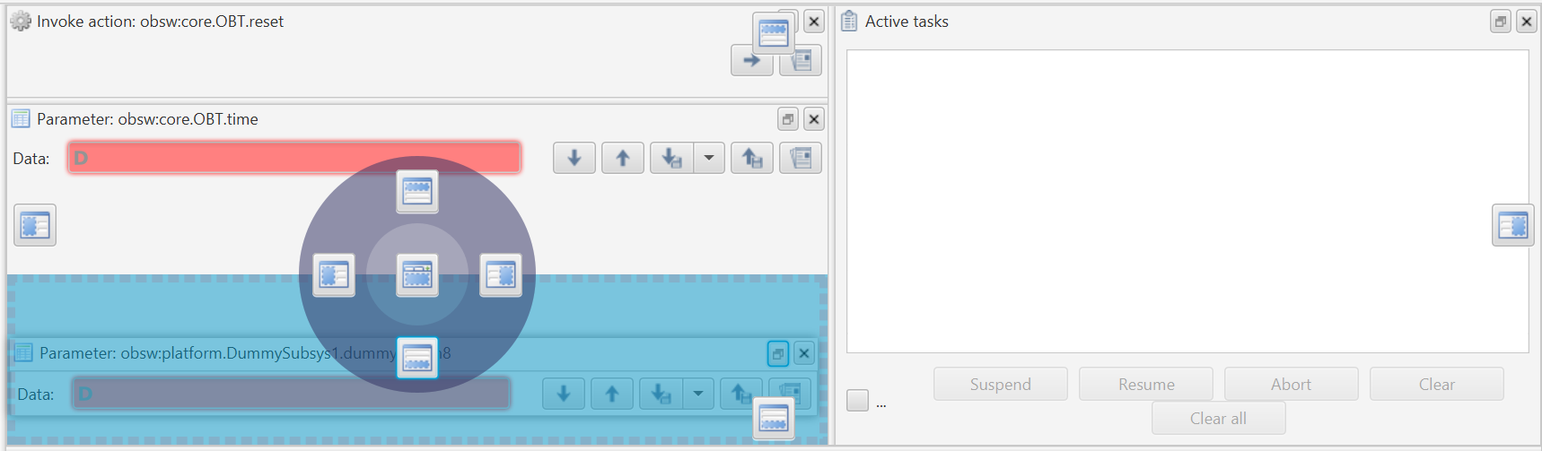
Once you are happy with a layout, it can be saved by right-clicking on the layout in the Mission Explorer and choosing Save (Figure 19), making sure that layout is currently selected. Switching to another layout or closing TMTCLab also has the effect of saving the current layout. To prevent a layout from being modified, it can be locked using the option in the context menu (Figure 19). This will keep the layout in the state it was when it was locked, regardless of whether windows are added, moved, or removed.
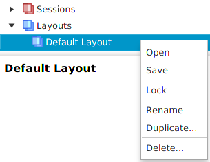
9.2. File
This section discusses the tools found under the File menu.
9.2.1. Sessions
Sessions allow the global configuration of TMTCLab to be changed. By switching sessions, the connection method, current layout, open deployments, as well as every other configurable part of TMTCLab can be switched between. An example use case is having a different session for the different deployments being developed for a specific spacecraft, loading in the different SCDBs for the deployments and using different layouts for each one.
TMTCLab initially starts in a default session, but new sessions can be created by right-clicking on the top-level Session item in the Mission Explorer (Figure 20). Existing sessions can be switched between by double-clicking on their icon in the Mission Explorer (Figure 21). Session layouts can also be modified and duplicated via the context menu available on each session.
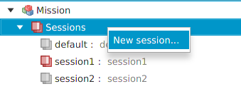
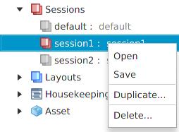
9.2.2. Deployment Management
The deployment management window allows you to add/remove targets and to set the deployments (SCDBs) for each of the configured targets (Figure 22). To add a new target, press the New target button. Selecting the target in the table then allows its deployment to be set using the Set deployment button, and choosing the corresponding SCDB.

9.2.3. Connection Window
The connection window allows you to configure and establish a connection to your deployment. To access this window click the 'Connect' button in the main window or go to File → Connect. It is possible to use a serial connection, a TCP client - where TMTC Lab acts as the client, a TCP server - where TMTC Lab acts as a server to be connected to, a UDP connection, an EGSE client, a Cortex TCP connection, or a qRadio TCP connection (Figure 23).
For certain connection types, the protocol framing in use can be specified as either Packet stream, KISS (TNC), or None.
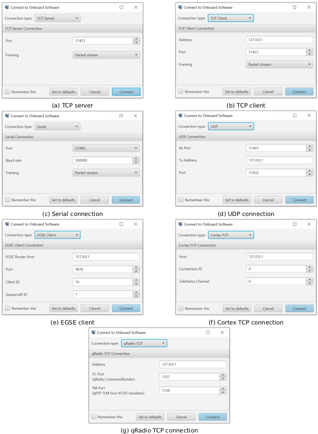
9.2.4. Protocol Properties
This section discusses the different options available in the Protocol Properties window and is organised according to the different sections in the window.
9.2.4.1. AX25
| Property | Description |
|---|---|
Use AX25 on uplink |
Set to true to enable AX25 uplink framing support |
AX25 uplink has start flag |
Set to true to enable AX25 uplink start |
AX25 uplink has end flag |
Set to true to enable AX25 uplink end flag field |
AX25 uplink has FCS |
Set to true to enable AX25 uplink FCS field |
Use AX25 on downlink |
Set to true to enable AX25 downlink framing support |
AX25 downlink has start flag |
Set to true to enable AX25 downlink start flag field |
AX25 downlink has end flag |
Set to true to enable AX25 downlink end flag field |
AX25 downlink has FCS |
Set to true to enable AX25 downlink FCS field |
AX25 FCS is MSB first |
Set to true if AX25 FCS is most-significant byte first |
AX25 Local callsign |
The AX25 callsign used in the ground software |
AX25 Remote callsign |
The AX25 callsign used by the remote entity |
AX25 Local SSID |
The AX25 SSID used in the ground software |
AX25 Remote SSID |
The AX25 SSID used by the remote entity |
9.2.4.2. CCSDS CFDP
| Property | Description |
|---|---|
CFDP APID |
The CCSDS APID to use for CCSDS CFDP transfers |
CFDP RX APIDs |
A list of the APIDs to use CCSDS CFDP reception |
CFDP Local Entity Id |
The CCSDS CFDP entity id for ground |
CFDP Ack Timeout |
The timeout for sending an Ack/Nack (in ms) |
CFDP PDU transmit gap |
The gap to wait between sending CCSDS CFDP file parts (in ms) |
CFDP PDU size |
The size in bytes of a CCSDS CFDP PDU |
CFDP Ack limit |
The number of ack/nack retries before timing out a CFDP transfer |
9.2.4.3. CCSDS Framing
| Property | Description |
|---|---|
Use CCSDS datalink (TM only) |
Set to true to use CCSDS framing on the downlink |
Use CCSDS datalink security |
Set to true to enable security in CCSDS SDLS framing |
Use CCSDS datalink |
Set to true to use CCSDS SDLS framing up/down |
TM Transfer Frame length |
The size in bytes of a CCSDS TM frame TC Transfer Frame length |
The size in bytes of a CCSDS TC frame |
TC Virtual Channel ID |
The Virtual Channel ID to insert in the header of a CCSDS TC frame |
TM Virtual Channel ID |
9.2.4.4. ECSS PUS
| Property | Description |
|---|---|
PUS C |
Set to true to use PUS-C over PUS-A |
PUS APID |
The CCSDS APID to use for ECSS PUS services |
PUS TM Time coarse bits |
The number of coarse time bits in a ECSS PUS packet |
PUS TM Time fine bits |
The number of fine time bits in a ECSS PUS packet |
9.2.4.5. General
| Property | Description |
|---|---|
Inhibit uplink |
Set to true to inhibit any transmission |
Spacecraft ID |
Used by CCSDS framing |
9.3. Monitors
This section explores the tools available under the Monitor menu.
9.3.1. Packet Monitor
The packet monitor (Figure 24) provides a log of packets exchanged between the ground and the on-board software. The different columns described in Packet monitor log columns contain decoded information relating to the packet.
Below the log of exchanged packets is further detail describing the selected packet, the left section presents some of the information given by the table in a different format as well as providing additional information such as the calculated CRC of the packet and also what the packet contained. The right section provides a human-readable description of the contents of the space packet.
The contents of the Packet Monitor can be exported to CSV using the right-click menu anywhere inside the log.
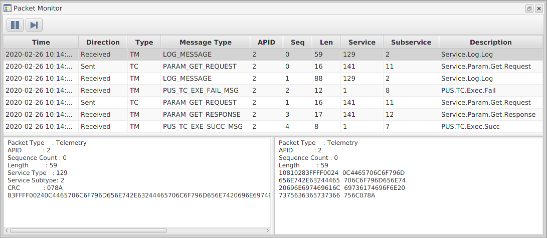
Time |
The time and date of the transaction. |
Direction |
The direction of the packet – whether it was a sent or received packet. |
Type |
The type of data the packet contains – either telemetry or a telecommand. |
APID |
Application process ID from the underlying CCSDS Space Packet. This is typically a single value, however, multiple IDs are supported by the GenerationOne FSDK. |
Sequence |
The packet sequence number. |
Length |
The byte count for the packet data. |
Service |
The identifier of the PUS service used in this transaction. |
Subservice |
The identifier of the PUS sub-service used in this transaction. |
Description |
A short description of the function of the packet. For example, whether the packet was an acknowledgement, or whether it was an action being invoked. |
9.3.2. Parameter Table
The Parameter Table displays the latest values of parameters, as shown in Figure 25. To add parameters to the table, drag and drop parameters from the Mission Explorer. Alternatively, double-clicking on an aggregation or beacon in the Mission Explorer (under Housekeeping) will open the Parameter Table populated with parameters in the aggregation.
When a parameter value is received (via a parameter get, beacon, or via the CLI) the corresponding parameter in the Parameter Table will also be updated. Using a beacon to retrieve parameter values allows for live values to be displayed in the Parameter Table as they are received.
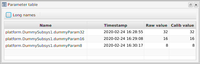
9.3.3. Activities
The activity window (Figure 26) can be opened using the button in the bottom left of TMTCLab, or by going to Monitors → Activities.
The window displays a tree of activities, e.g. get, set, downlink, uplink, invoke, which are currently running or have completed. The nesting of activities indicates a parent-child relationship. For example, the top-most activity in Figure 26 was triggered by getting the value of a parameter. This activity then started a PUS get-request to perform the task of asking the on-board software for the value of the parameter.
Each entry in the list details the current state of the activity. These states are:
-
Idle, while the activity is waiting to be started.
-
In-progress, while the activity is running.
-
Completed, if the activity finishes successfully.
-
Timeout, if the activity takes too long to complete.
-
Aborted, if the activity is manually aborted via the Abort button on the Activity Window (Figure 26).
-
Suspended, if the activity is manually suspended via the Suspend button on the Activity Window (Figure 26). Note that suspended activities can be restarted using the Resume button.
By default, completed activities will be removed from the list once they are completed. To prevent this behaviour, check the Hold checkbox.
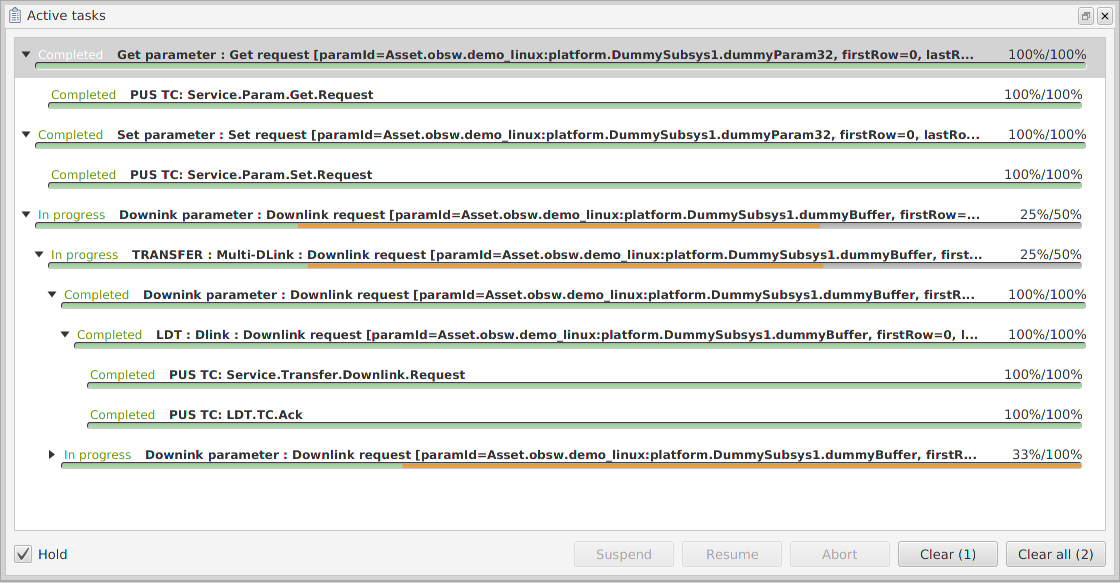
9.3.4. Transfers
The transfer window (Figure 27) displays a subset of the activities in the Activity monitor and can be opened using the Transfers button on the toolbar, or by going to Monitor → Transfers. When a parameter is downlinked/uplinked the transfer will be added to the transfer list, detailing the current state of the transfer.
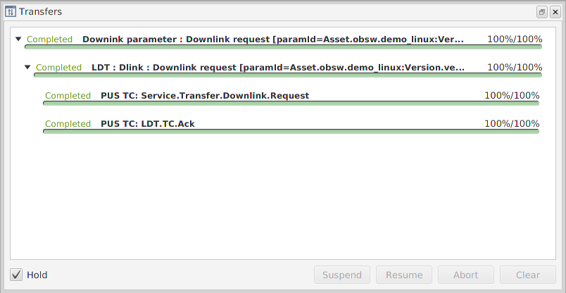
If any errors are encountered with a transfer, then it will remain in the list. It’s possible to suspend a transfer, which will be picked up again upon resumption unless the transfer has timed out. Clicking abort on a transfer will perform an abort request to stop further packets being sent.
9.3.5. Command Line Interface
The Command-line interface (CLI), shown in Figure 28, allows interaction with onboard software via scripts. A script is composed of a simple set of instructions for getting, setting, downlinking, and uplinking parameters; querying the dimensions of a parameter; and invoking an action.
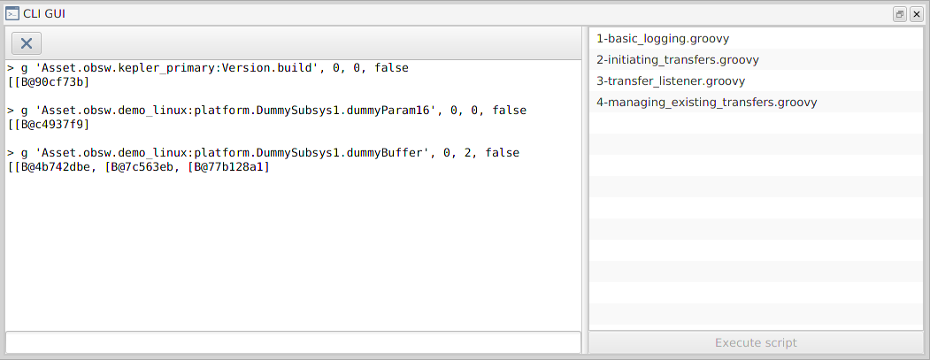
Commands can be run from this window and the output displayed to the CLI window. This information first prints out a readable echo for the telecommand that has been sent and then prints what telemetry was returned for the command. This could be either an ACK, a NACK, values requested or a response.
The history of commands run via entry into the CLI can be obtained using the arrow keys on the keyboard while the CLI text-field is focused. The up arrow moves backwards in the history one command, and the down arrow moves forward in the history. To aid the discovery of commands, when a command is performed via the GUI, such as a parameter-get via the parameter dialog (Section 9.1.2.1), the command to run this activity is also placed into the history.
9.3.5.1. Get
To get a parameter, you first type ‘g’ followed by the parameter name, the first row to start retrieving from, the last row retrieved, and whether to resize (discussed in subsection Section 9.3.5.7). This command will then return the range of rows that you specified for that parameter. Note that the rows are zero-indexed. As an example, to get the values of dummyBuffer from its second row to its fourth use the following command:
g 'Asset.obsw.demo_linux:platform.DummySubsys1.dummyBuffer', 1, 3, false9.3.5.2. Set
To set a parameter, first type ‘s’ followed by the parameter name, the first row to be set and the data to set in hexadecimal with spaces separating each row. The first row is zero-indexed and the range is inclusive. This command will then set the values given starting from the first row specified. For example, to set rows 2 and 3 of dummyBuffer to 0x01 and 0x02 use the following command:
s 'Asset.obsw.demo_linux:platform.DummySubsys1.dummyBuffer', 1, [0x01, 0x02], false9.3.5.3. Downlink
Get (and set) telecommands are limited to a single packet. For large data transfers, parameters will need to be downlinked using LDT. To downlink a parameter, you first type ‘downlink’ followed the parameter name, the first row to read from, the last row to read to, and the row size in bytes. The row range is inclusive This command will allow up to 16384 bytes of data to be retrieved in a single transfer. For example, to downlink the data from parameter dummyBuffer from row 2 to 127 use the following command:
downlink 'Asset.obsw.demo_linux:platform.DummySubsys1.dummyBuffer', 1, 126, 19.3.5.4. Uplink
Similar to downlink, the uplink telecommand allows for more data to be sent to a parameter. To uplink to a parameter, you first type ‘uplink’ followed by the name of the parameter, the values of the rows to uplink, the first row to set and then the final row to be set. For example, to uplink the values 0x01 and 0x02 into the second and third rows use the following command:
uplink 'Asset.obsw.demo_linux:platform.DummySubsys1.dummyBuffer', [[0x01], [0x02]], 1, false9.3.5.5. Query
To get the dimensions for a parameter, use the command ‘q’ followed by the name of the parameter you would like to query. This returns the row count and the bytes being used by the parameter. For example, to query the dimensions of dummyBuffer use the following:
q 'Asset.obsw.demo_linux:platform.DummySubsys1.dummyBuffer'9.3.5.6. Invoke
To invoke an action, use the ‘i’ followed by the name of the action you wish to invoke, followed by any arguments that the action may take, represented as an array of bytes. The argument should match the signature for the action as given by the deployment documentation.
For example, to invoke action Asset.obsw.demo_linux:core.Storage.wipe (which has a signature with a raw2 argument) using the decimal 1 as the argument use the following command:
i 'Asset.obsw.demo_linux:core.Storage.wipe', [0x00, 0x01]9.3.5.7. Resize
It is possible to specify that a get or set command should be called with resize set by setting the resize flag at the end of the command. Resize behaves differently for 'get' and 'set' requests, as discussed below.
9.3.5.8. Resize Get
There are two cases that could occur if performing a get command where resizing is enabled:
-
The number of rows requested is smaller than or equal to the number of rows present. In this case, the requested rows are returned.
-
The number of rows requested is larger than the number of rows present. In this case, all the rows of the parameter are returned.
Therefore, resizing can be used to get all the rows of a parameter whose size is unknown. For example, to get all the rows for parameter BaseAggregator.paramListPacked, you could specify the last row larger than the number of rows the parameter contains (3 by default), and flag for the command to resize the row for you by setting the last argument to true. To do this, you could use a command like the following:
g 'Asset.obsw.demo_linux:cdh.BaseAggregator.paramListPacked', 0, 5, true9.3.5.9. Resize Set
To resize a set request, set the resize flag to true (the last argument to set). This will cause the parameter on the flight-side to match the size of the data supplied with the parameter set request.
If resizing is applied to a set request, then the parameter’s last row index will be made to match the last row index supplied with the request. More specifically, the three cases that could occur if resize is requested are:
-
If the last row index supplied in the set request is larger than the current last row index, then the parameter will be made larger (up to its maximum size) to accommodate the extra data.
-
If the last row index supplied in the set request is smaller than the current last row index, then the parameter will be truncated so its last row index is made to match the supplied last row index.
-
The data matches the size of the parameter. In this case, the parameter is simply set to the new value.
For example, to overwrite all the rows stored in parameter BaseAggregator.paramListPacked with 0x0010000600000000FFFF0000, use the command:
s 'Asset.obsw.demo_linux:cdh.BaseAggregator.paramListPacked', 0, [[0x00, 0x10, 0x00, 0x06, 0x00, 0x00, 0x00, 0x00, 0xFF, 0xFF, 0x00, 0x00]], true9.3.5.10. CLI Summary
As a general rule, on the CLI:
-
action and parameter names are always given as strings;
-
row numbers are always specified in decimal;
-
data can be specified in hexadecimal (with the prefix 0x) binary (with the prefix 0b), octal (with the prefix 0) or decimal with no prefix at all;
| Command | Use | Example |
|---|---|---|
|
Get the values of a parameter using an inclusive row range. |
|
|
Set the values of a parameter starting from a given row using the provided rows. |
|
|
Downlink the values of a parameter using an inclusive row range. |
|
|
Uplink the provided rows to a parameter. |
|
|
Query the dimensions of the parameter; the amount of rows and the overall size of the parameter. |
|
|
Invoke an action using the provided argument. |
|
9.4. Housekeeping
This section discusses the tools found under the Housekeeping menu, as well as in the Mission Explorer.
9.4.1. Aggregations
Aggregations pack together multiple parameters into a single parameter, which can later be decoded into separate parameters.
Using New aggregation from file or Multiple new aggregations from files will create new aggregations from YAML files created using the Aggregation Builder (see Section 9.5.3). Aggregations created will be available under Aggregations in the Mission Explorer, and under the drop-down menus in the Decode Data Log and Decode Event Log tools.
9.5. Tools
This section details the tools available under the Tools menu.
9.5.1. Event Log Decoding
Going to Tools → Decode event log will bring up the window to decode an EventLogger’s contents, as displayed in Figure 34. The tool can decode either the data from a recent parameter get or downlink. Once decoded the output can then be exported as a Comma Separated Value (CSV) file to be loaded into a spreadsheet. Section 9.6.2.4 provides a demonstration of how to use this tool.
9.5.2. Data Log and Aggregation Decoding
Similar to Event Log Decoding, it’s possible to decode the output from a DataLogger. As with the Event Log Decoding, you can use either the values from a recent parameter get or from a downlinked binary file.
DataLoggers typically use the output from aggregators. Therefore, to decode a DataLogger, the corresponding aggregation is required. This can be supplied either by selecting an aggregation from the drop-down menu. Alternatively, an aggregation definition YAML file can be supplied which can be generated using the aggregation builder (Section 9.5.3).
Once you have set a source and definition, you can decode the source and you will get output similar to Figure 29. Section 9.6.3 provides a demonstration of how to use this tool.
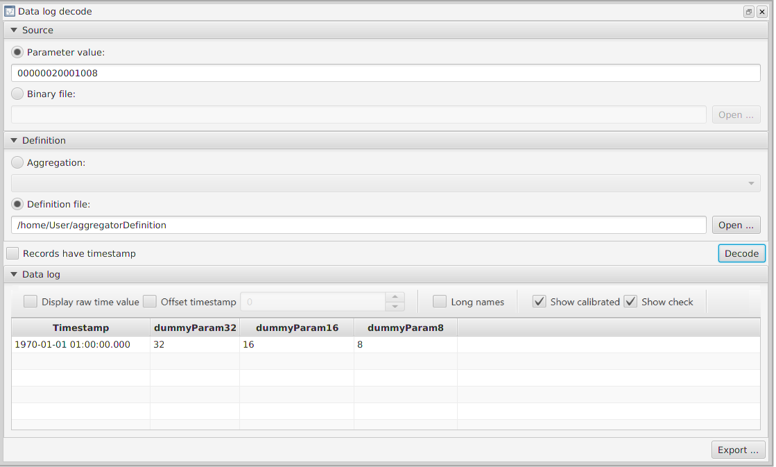
9.5.3. Aggregation Builder
The Aggregation Builder tool (Figure 30) displays the parameters being packed together in an aggregation, as well as allowing aggregations definitions to be edited.
To retrieve an aggregation definition, select the aggregation of interest from the drop-down menu and press the Load from aggregator icon, which will get the definition from the on-board software.
To add new parameters to the aggregation, drag and drop parameters from the Mission Explorer onto the aggregation viewer. To delete parameters from the aggregation, select the appropriate row in the table and press the delete icon. Once you are done editing, the updated aggregation is sent to the OBSW using the Send to aggregator icon.
A YAML data definition file can also be created using the Save to portable format icon, which can then be used decode a DataLoggers (Section 9.5.2) and for live housekeeping (Section 9.4).
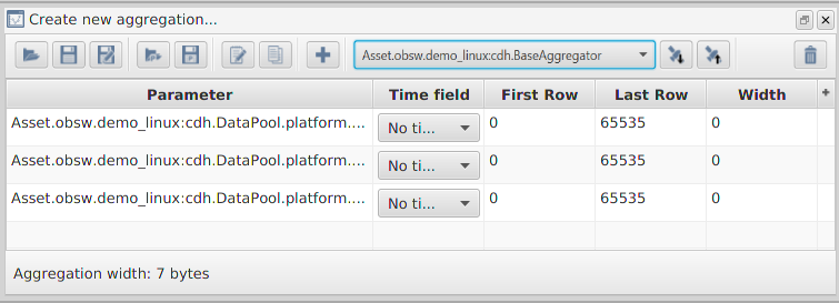
9.5.4. Time action schedule builder
The Time Action Schedule Builder (Figure 31) allows schedules dependent on time to be constructed and can be opened by going to Tools → Time action schedule builder.
Schedule entries (rows in the table) uploaded to the target can be executed at an absolute time; the onboard time (OBT) at which the entry will be executed. Alternatively, the entry can be run at a relative time; the time at which the entry will be executed is given as an offset to the OBT.
Once a schedule entry’s relative or absolute time is reached, a parameter or action associated with the entry can be set or invoked, respectively. The schedule can later be downlinked to check whether it has been executed.
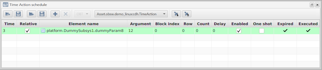
9.5.5. Periodic action schedule builder
The Periodic Action Schedule Builder(Figure 32) allows the construction of schedules that run at regular intervals and can be opened by going to Tools → Periodic action schedule builder. Once uploaded, an entry in the schedule is executed every period seconds, and are run a total of multiplier times, each time either invoking an action or setting a parameter. The schedule can later be downlinked to check whether it was executed.
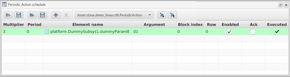
9.5.6. Event action schedule builder
The Event Action Schedule Builder (Figure 33) allows the construction of schedules that run according to whether certain events occur, and can be opened by going to Tools → Event action schedule builder. Each entry in the schedule contains an event that, when occurs, causes an action to be invoked or parameter set. The schedule can later be downlinked to see whether it was executed.
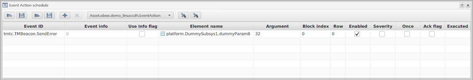
9.6. Worked examples
This next section will take you through the different ways that you can interact with the TMTCLab ground software via a walk-through.
9.6.1. Monitoring parameters
In this section, we will set up a Monitor for a dummy parameter to check whether it goes out of range. When the parameter goes out of range, an event will be raised. This event will be listened to and will trigger an action to reset the monitored parameter.
9.6.1.1. Adding a parameter to monitor
First, we will set up the monitor. In the Mission Explorer window, select cdh.BaseMonitor.CheckListPacked. You should see the description of this parameter that explains how the packed record is broken down. Querying this parameter will show that there is currently a single parameter being monitored.
For the purposes of this demo, we want to monitor a new parameter DummySubsys1.dummyParam16. To do this we want to append DummySubsys1.dummyParam16, which has ID 0x000E0001, to the end of CheckListPacked.
First, we will need to set up a packed record in the Data field. As per the parameter’s description, the record starts with the parameter ID, 0x000E0001.
Next is the row number for the parameter, which is 0 given that the dummy parameter is not a vector parameter. Next we specify the valid range for the parameter value to be between 0x02 and 0xF0.
Next, we set a threshold for how many times the check should fail before an event is raised. We’ll keep it simple and set this to 0 so that an event is raised as soon as a check fails.
Next, we specify the events that should be raised if the parameter does go out of range, for which we’ll use the default for monitor check failure: 0x003C for both, lower and upper bounds.
After that, we specify what group to place this entry. There are 4 zero-indexed groups that a check can be in. Each of these groups has a specified threshold of how many entries within that group have to fail. Once enough failed checks have taken place, the event of the causing check will be raised. As we’re going for a single individual check, we’ll leave it in group 0, which is initialised to have a threshold of 0. When a group has a threshold of 0, events are immediately raised for any failing check in that group, which is what we want.
Finally, we specify the flags, although there’s only the enabled flag that we need to consider and we want this to be enabled (so set that bit to 0x01). With this data set out in the manner described by the parameter information, we should end up with the following in the Data field:
000E00010000000000F0000000020000003C003C0001To append to CheckListPacked, we want to set the First row value to 1 (the Last row value will also be 1) and make sure that Resize is checked. Now hit the Set icon, i.e. up arrow, which should successfully append this row to the list. This can be checked by querying the parameter. The Current size should now be 2 rows. If you get back the parameter, with First row being 0 and Last row being 1, you should see the original record followed by the one we just added.
9.6.1.2. Enabling the monitor
Next, we need to enable the monitor itself, as it is disabled by default. To do this, select the enable parameter on BaseMonitor, enter 01 into the Data field and then set the parameter. The monitor is now active and will now check the parameter that we set up according to the refresh rate that was set in the deployment.xml file.
We can test that the monitor works by setting the parameter (DummySubsys1.dummyParam16) to a value that is outside of the range that we set, for example, 0x00. Within the refresh rate time, you should see a packet received with an 'Event' description and an event ID of 60 (0x003C), which confirms that the monitor is functioning. The event should also be visible in the Event window in TMTCLab and should be displayed in a more readable fashion as “Monitor.CheckFailedError”. The event will only be raised once and won’t be raised again unless the parameter is set back in range and then set out-of-range once more.
9.6.1.3. Setting Up an Event-Action
Next we want to set up an event-action so that we can reset the parameter to it’s default value. Let’s first test that the reset functions correctly, invoke the DummySubsys1.reset() action and then check that DummySubsys1.dummyParam16 has reverted back to 0x0010.
Once you have confirmed that resetting the parameter works as expected, right-click on the EventAction and open the Administer dialog. This allows you to set a parameter or perform an action when an event occurs. When the Monitor.CheckFailedError (which has an ID of 0x000D0000) occurs we want to invoke the DummySubsys1.reset action. To do this, press the add icon to add a new entry to the schedule, and enter Monitor.CheckFailedError into the Event ID. Next, choose platform.DummySubsys1.reset as the Element name, i.e. the action that will be invoked when the event occurs. There is no argument to this action, and so Argument can be left blank.
For the flags, Use info flag can be disabled as, otherwise, the entry will only execute if both the event ID and info match the raised event. The Enabled flag should be checked to allow the entry to run. Severity should be disabled as we want the entry to trigger when a specific event ID is matched, not just the 'severity' part of the event ID. Once should be disabled to allow the entry to be triggered multiple times for easy debugging. Ack flag can be enabled or disabled. More documentation for these fields can be found under the documentation for EventAction.entryListPacked.
The schedule can now be uploaded using the upload button, pressing OK on the confirmation dialog to overwrite the spacecraft’s existing onboard schedule.
To test the event-action, first set EventAction.enabled to 1, then set DummySubsys.dummyParam16 to an out-of-range value. The monitor should raise an event and then event-action should reset the parameter back to the default value. In the Packet Monitor you should see two events: one from the Monitor, indicating that the check failed, and one from the EventAction component, indicating that it successfully invoked the action. If you query the DummySubsys.dummyParam16 parameter again, you should find that its value has been reset.
9.6.2. Downlinking a Data Storage Channel
As explained in Downlink (Section 9.3.5.3), 'Get' telecommands can only retrieve up to the maximum amount of data that can be stored in a telemetry packet. Typical deployments include loggers that use storage channels to store information such as raised events and telecommands. The parameters these loggers store their data into are typically too large for a single packet. To provide an example of how to get the data in the storage channel, we’ll look at how to get the data saved by the EventLogger.
9.6.2.1. Finding the EventLogger Channel Number
The EventLogger has a parameter called channelId, which will return the storage channel ID currently being used by the logger. Get this value and make a record of it. On demo_linux, this value should be 1.
9.6.2.2. Querying the EventLogger Storage Channel
Now that we know the channel number, we can find out how large a single storage row is for this channel. Go to the Storage component and get the rowLength parameter at the row corresponding to the channel ID for the EventLogger (i.e. row 1). The EventLogger’s row should be 12 bytes long (i.e. the Data field should read hex `0000000C). Next, get the Storage.numRows again using the channel ID as the row index. This will tell you how many rows are currently being used by the storage channel. The logger stores one event record in each row of the storage channel.
9.6.2.3. Downlinking the Data
Now we know how much data to downlink. The maximum amount of data that can be downlinked per transfer is 16384 bytes. Thus if the data being stored exceeds this, then multiple downlinks will need to be performed. As an example, to downlink the first 10 rows of the EventLogger’s storage channel, select the `Storage.channelContent parameter. Next, set the parameter index in block value to the EventLogger's channel ID and then set the row range from 0 to 9. Now click the Downlink icon and a popup menu should request the file you wish to downlink data to.
The structure of the stored data is explained in the `EventLogger’s documentation (as viewed in the Spacecraft Explorer Section 9.1.1). It is possible to retrieve data stored by other loggers in a similar manner.
9.6.2.4. Decoding the EventLogger
As explained in Section 9.5.1, it’s possible to decode the data that’s logged by the EventLogger. To do this, either 'get' or 'downlink' (if there are many rows) the storage channel rows that you want to decode. After that, open Tools → Decode event log.
Next, if you performed a 'get' then paste the parameter value from the Storage.channelContent data field into the Parameter value field of the Event log decode window. Alternatively, if you downlinked the contents of Storage.channelContent, then choose the appropriate file using the Binary file chooser.
Finally, Decode and you should see the Event Log table fill up with the rows similar to Figure 34. Note that the time is the onboard time.
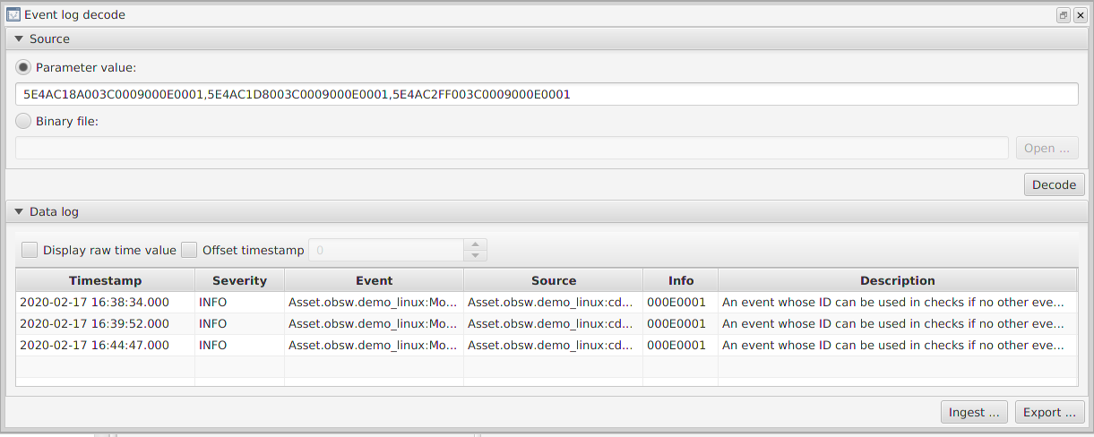
9.6.3. Decoding the DataLogger
This section explains how aggregated data can be decoded using the Decode Data Log tool.
9.6.3.1. Downlinking data to decode
First, we need some data to decode. In demo_linux, there’s a DataLogger, cdh.logging.BaseLogger, for which you can decode the channelContents, as explained in Section 9.5.2. In order to downlink BaseLogger’s logged rows, first check which storage channel the `BaseLogger is using by getting BaseLogger.channelId.
Next, we need to determine the number of rows present in Storage.channelContent at the storage channel corresponding to the channel ID used by BaseLogger. To do this, perform a get of Storage.numRows at the row for BaseLogger’s storage channel ID (on `demo_linux this should be 3).
Alternatively, you can query the number of rows by setting parameter index in block of Storage’s `channelContent to be BaseLogger’s channel ID. Then, query the number of rows using the question mark in the top-right of the `Storage.channelContent dialog.
It’s likely there are no rows present, as BaseLogger is disabled by default. To add some rows, enable BaseLogger and then wait for some rows to be logged. Alternatively, invoke the BaseLogger.log action to create logs and then invoke the BaseLogger.flush action to store the logs. Once there are rows in the BaseLogger’s storage channel, downlink the channelContent from Storage.
9.6.3.2. Generating an Aggregation definition
The BaseLogger logs the output from the BaseAggregator. To decode the stored log data, you first need to create a data definition from the BaseAggregator.
As explained in Section 9.5.3, you can do this with the Aggregation Builder. Open the Aggregation Builder by going to Tool → Aggregation Builder. Next, select the BaseAggregator from the drop-down menu and press the Load from Aggregator button to get the aggregation from the spacecraft. This will populate the table with each parameter in the aggregation. Finally, click Save to portable format to save the aggregation in a YAML format which can be read by the Data Log Decode tool.
9.6.3.3. Decoding
Now, open Tools → Decode data log. Choose the appropriate downlinked data for the binary file and YAML file for the aggregation definition. Next, press Decode and you should now see a screen similar to Figure 29. As with the event log, the timestamps are the onboard time when the log was created.
9.6.4. Wiping a Full Data Storage Channel
Eventually, your storage channels will fill up. You can check whether a storage channel is full through the isFull parameter in the Storage component, with a flag for each storage channel. Note, however, that channel 0 is a NULL channel and so should not be accessed.
While testing with TMTCLab, TCLogger component’s channel is likely to fill up. You can find out the ID of the channel used by this component through it’s channelId parameter. If the channel does fill up, then TCLogger will raise an event informing you of such.
If there are a lot of events being issued, it’s also possible that the EventLogger component’s storage channel will fill up, and you can similarly find out the channelId. To avoid a flood of events, if the `EventLogger’s channel is full then an event won’t be raised. Therefore, under normal operation, it is worth periodically checking whether the storage channel is full.
When you have the ID of the channel that you wish to wipe, you simply invoke the Storage.wipe action, passing in the channel ID as the argument (as two bytes in network byte-order).
9.6.4.1. Demo Linux channels
In the demo_linux deployment, there are 3 channels that are assigned as follows:
-
the
EventLoggerstorage channel, each row contains an event which occurred on board; -
the
TCLoggerstorage channel, each row contains a telecommand received from ground (padded to 256 bytes); -
the
BaseLoggerstorage channel, each row contains a bit-packed telemetry record which is specified by theBaseAggregator.
9.6.5. Live Housekeeping
It is possible to view live parameter values in TMTCLab. Live values are shown in the Parameter table window, as mentioned in Section 9.3.2.
For demo_linux, there is only one TMBeacon entry, which uses the BeaconAggregator. Before you can add the housekeeping definition for the beacon, you need a new aggregator definition to match the BeaconAggregator. To do this, use the Aggregation Builder to retrieve the aggregation definition for the BeaconAggregator. Next, save this definition as a YAML file (these are similar steps to [p:lab_GeneratingAnAggregationDefinition]). Finally, use Housekeeping → New aggregation from file to add a new aggregation using the created YAML file.
Now a new beacon mapping can be created. To do this, go to Housekeeping → New beacon mapping. Give the beacon an ID and select the aggregation just created. The mapping should now appear in the Mission Explorer under Housekeeping/Beacon map.
Before you can see live housekeeping, the TMBeacon component will need to be enabled using the cdh.tmtc.TMBeacon.enable parameter. Once enabled, you should see housekeeping packets start appearing in the Packet Monitor window. Opening the Parameter Table by double-clicking on the created aggregation or beacon mapping in the Mission Explorer, you should see the reported value of each parameter being updated, like in Figure 25.
10. Distributed Systems
This chapter describes how to build and run distributed Linux deployments included with the GenerationOne FSDK.
The intention is to give you a practical example of how multiple deployments can interact with each other and how to access parameters and actions from one deployment whilst being connected to the other.
An example of this would be a spacecraft with a platform computer and a payload computer where the radio link is connected to the platform computer and an onboard data bus connects the payload computer to the platform computer.
We have created two deployments to demonstrate the basics of the distributed systems capabilities included with the GenerationOne FSDK, demo_linux_dist_1 and demo_linux_dist_2.
Throughout this section we will refer to demo_linux_dist_1 as deployment 1 and demo_linux_dist_2 as deployment 2.
10.1. Communications Stacks
The comms stack for deployment 1 includes a ground connection to the deployment via a TCP connection, while deployment 2 has no direct communications with the ground.
The two deployments have been set up so that TMTC Lab can only directly connect to deployment 1 target but is able to interact with deployment 1 and deployment 2.
The two deployments communicate with each other via a UDP connection, this allows remote requests from ground to the demo_linux_dist_2 to be routed via demo_linux_dist_1.
A visual representation of the comms stack for the two deployments can be seen in Figure 35.
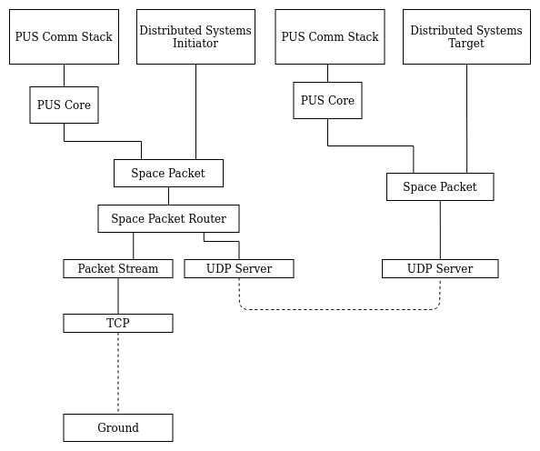
10.2. Deployment XML
The two distributed systems demo deployments are based on the demo_linux deployment, we will cover the notable changes here.
Ground Connection
The ground to deployment comms stack has been removed from the second deployment as we do not want to communicate with it directly, only via our connection to the first deployment. The ground to deployment 1 comms stack remains the same, with a TCP server running on deployment 1, with the client connection from TMTC Lab.
Distributed Systems Initiator
Deployment 1 contains the AAS and PAS initiator component instances.
<!--Distributed Systems Initiator (deployment 1 <-> deployment 2)-->
<!-- AAS Out -->
<Component name="remote.services.AASMessaging"
type="io.AMS.AMSInitiator">
<Connections>
    <Services>
    <Service name="serviceInitiator"
        component="comms.SpacePacket" service="dataPacket" channel="1" />
    </Services>
</Connections>
<Tasks>
    <SporadicTask name="receive" priority="2" />
    <SporadicTask name="waitForSendComplete" priority="2" />
    <SporadicTask name="amsCompleteTimeout" priority="2" />
</Tasks>
</Component>
<Component name="remote.services.AASProxy"
type="component.AAS.AASInitiator">
<Connections>
    <Services>
    <Service name="remote"
        component="remote.services.AASMessaging" service="target" />
    </Services>
</Connections>
</Component>
<!-- PAS Out -->
<Component name="remote.services.PASMessaging"
type="io.AMS.AMSInitiator">
<Connections>
    <Services>
    <Service name="serviceInitiator"
        component="comms.SpacePacket" service="dataPacket" channel="2" />
    </Services>
</Connections>
<Tasks>
    <SporadicTask name="receive" priority="2" />
    <SporadicTask name="waitForSendComplete" priority="2" />
    <SporadicTask name="amsCompleteTimeout" priority="2" />
</Tasks>
</Component>
<Component name="remote.services.PASProxy"
type="component.PAS.PASInitiator">
<Connections>
    <Services>
    <Service name="remote"
        component="remote.services.PASMessaging" service="target" />
    </Services>
</Connections>
</Component>
Distributed Systems Target
Deployment 2 contains the AAS and PAS target component instances.
<!-- Distributed Systems Target -->
<!-- AAS In -->
<Component name="remote.services.AASMessaging"
type="io.AMS.AMSTarget">
<Connections>
    <Services>
    <Service name="initiator" component="comms.SpacePacket"
        service="dataPacket" channel="1" />
    <Service name="serviceTarget"
        component="remote.services.AASProxy" service="remote" />
    </Services>
</Connections>
<Tasks>
    <SporadicTask name="receive" priority="2" />
    <SporadicTask name="waitForReplyComplete" priority="2" />
    <SporadicTask name="sendCompleteServiceTarget"
    priority="2" />
    <SporadicTask name="requestCompleteServiceTarget"
    priority="2" />
</Tasks>
</Component>
<Component name="remote.services.AASProxy"
type="component.AAS.AASTarget" />
<!-- PAS In -->
<Component name="remote.services.PASMessaging"
type="io.AMS.AMSTarget">
<Connections>
    <Services>
    <Service name="initiator" component="comms.SpacePacket"
        service="dataPacket" channel="2" />
    <Service name="serviceTarget"
        component="remote.services.PASProxy" service="remote" />
    </Services>
</Connections>
<Tasks>
    <SporadicTask name="receive" priority="2" />
    <SporadicTask name="waitForReplyComplete" priority="2" />
    <SporadicTask name="sendCompleteServiceTarget"
    priority="2" />
    <SporadicTask name="requestCompleteServiceTarget"
    priority="2" />
</Tasks>
</Component>
<Component name="remote.services.PASProxy"
type="component.PAS.PASTarget" />
Routing
Routes for the Action Access System (AAS) and Parameter Access System (PAS) have been added to the first deployment as follows, note the target has been set to point towards the second deployment. Local parameter access in the first deployment will behave as normal, only requests meant for the second deployment will be routed to the second deployment.
<Routes>
    <Route target="2" component="remote.services.AASProxy"
    service="proxy" />
    <Route target="2" component="remote.services.PASProxy"
    service="proxy" />
</Routes>
10.3. Working with the deployments
-
Firstly build and run both
demo_linux_distdeployments, since the connection between the deployments uses UDP, the order in which the deployments are run does not matter. -
TMTC Lab can then connect to the TCP server running on
demo_linux_dist_1via port 51423 as seen in Figure 36 -
Next you can set up the two deployments as targets in TMTC Lab, loading the Spacecraft Database for each deployment into a separate target, see Figure 37.
-
Once the two Spacecraft Databases have been loaded, it is important to configure them correctly. The default settings for the first deployment are fine in this instance, but the second target will require a small change. The PUS APID for the second deployment must be updated to match the APID used in the deployments init data, in this case '4'. If you right click on the second target and select "Configure target" you can update the APID to match Figure 38
-
Now that the two targets have been set up we are able to interact with both deployments as if we have a direct connection to both, when in fact we are only connected directly to the first deployment. This is possible because any requests meant for the second target are routed from deployment 1 to deployment 2.
-
You can now experiment by getting and setting parameters on the two deployments, as well as invoking actions.
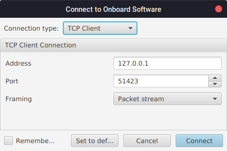
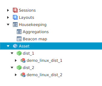
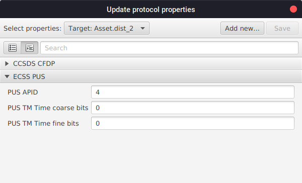
11. Linux Onboard Computer Platform Guide
The GenerationOne FSDK supports software development, testing and deployment running on the Linux platform. The default build configuration for most projects is to use linux. Other linux platforms, running on ARM processors, are supported. Officially supported are the Rapsberry Pi 2, Raspberry Pi 3, Beaglebone Black and Xiphos Q7. However their .mk files in the build_system project can be duplicated and adopted to support similar linux-based platforms.
There are demonstration deployments for different linux platforms:
-
demo_linux -
demo_bbb -
demo_pi-
default’s to build for Raspberry Pi 3, but can also build for Raspberry Pi 2
-
-
legacy_tutorial1 -
legacy_tutorial3
While most unit tests can be run on other platforms, while developing a component it is convenient to be able to run the unit tests on Linux.
11.1. Linux Image Management
Multiple gen1 binaries can be stored and managed on a linux onboard computer. They are managed by a monitored flight control script.
The gen1-flightcontrol shell script is designed to safely boot gen1 binaries and reload any dependent kernel modules. A system daemon manager such as systemd is used to ensure the gen1-flightcontrol launcher script stays running.
A gen1 component named BootControl is used to select and validate boot images. Image upload is not done by this component. That is expected to be done via CFDP.
The launcher communicates the currently executing image slot to the BootControl component through use of a 'current_image' file. The BootControl component in turn communicates back the next image to boot via a 'next_image' file. Each primary image has a md5 checksum file loaded along side it. If a primary image fails checksum validation, the failsafe will be booted instead.
11.1.1. Requirements
-
The
BootControlcomponent included in your gen1 deployment. -
An
md5sumtool included on your onboard computer. -
Systemd or an equivalent init system included on your onboard computer.
11.1.2. Setting up the launcher
The launcher should be copied to the onboard computer unmodified. It can found at 'gen1/OBSW/Source/linux/system/gen1/gen1-flightcontrol'.
Configuration of the launcher is done via a sourced shell script. It expects the configuration to be named 'gen1-launcher.conf' and be placed in the same directory as the script.
An example of a configuration file can be found at gen1/OBSW/Source/linux/system/
gen1-launcher.conf.
In the file you’ll find several shell variables being set. All of these variables apart from the optional 'KERNEL_MODULES' needs to be configured.
| Shell Variable | Description |
|---|---|
BINARY_NAME |
The name of the compiled gen1 executable. Each gen1 binary on the system should have the same name. |
BINARY_MD5_NAME |
The name of each md5 checksum file which will be used to validate its corresponding gen1 binary. |
PRIMARY_IMAGE_DIR_PREFIX |
The base directory of primary image folders. Subdirectories of this folder will be named '1' through '9'. |
FAILSAFE_IMAGE_PATH |
The path to the failsafe gen1 binary. |
FAILSAFE_IMAGE_DIR |
The directory of the failsafe gen1 binary |
KERNEL_MODULES |
The space separated list of kernel modules which should be reloaded before starting the gen1 binary. |
NEXT_IMAGE_FILE |
This file will be used to communicate which image slot should be loaded next. The location of the file should be in writeable memory. |
CURRENT_IMAGE_FILE |
The current image file is used to communicate the current slot number between the launcher and the currently executing gen1 binary. |
FAILSAFE_IMAGE_INDEX |
The slot number of the failsafe image index. This should be left set to '0'. |
11.1.3. Systemd Setup
Systemd is used to launch and monitor the gen1-flightcontrol launcher script. Users are free to use their own init system choice. However, these instructions will only provide a guide on systemd usage.
An example of a systemd service used to control the launcher can be found at 'gen1/OBSW/Source/linux/system/gen1-flightcontrol.service'. You should only need to modify two lines of this file. The 'ExecStart' line should be modified to point to the correct location of the gen1-flightcontrol launcher script. 'WorkingDirectory' should be modified to point to a modifiable folder. All relative paths specified in gen1 init.c files will be based off this given workspace root.
The gen1-flightcontrol.service file should be placed at '/etc/systemd/system/
gen1-flightcontrol.service'. To enable the service to run when the board is booted, execute the following as root.
# systemctl enable gen1-flightcontrol.service11.1.4. Gen1 binary locations
The failsfe image should be placed at the location specified by the FAILSAFE_IMAGE_PATH variable in the launcher configuration script.
Primary images should be placed under
PRIMARY_IMAGE_DIR_PREFIX/x/ where the prefix is the value specified in the launcher configuration and x is a number between 1 and 9. This provides 9 primary image slots.
Each primary image should also have an accompanying md5 checksum file. The checksum file name should match the one specified in BINARY_MD5_NAME when writing the launcher config. MD5 checksum files can be gererated using the following command.
$ md5sum 'gen1-binary' > 'gen1-binary.md5'Note - The file listed in the output of md5sum should not have any path prefixing the file name.
Eg 'd41d8cd98f00b204e9800998ecf8427e gen1-binary' is fine while 'd41d8cd98f00b204e9800998ecf8427e workspace/gen1-binary' is invalid.
As mentioned earlier, kernel modules can also be loaded by the gen1 launcher. A safe version of each kernel module should be placed under FAILSAFE_IMAGE_DIR. Any newer versions of the module should be placed into the same folders as the primary images. Kernel modules in the primary images folders are also expected to contain a checksum file. When a primary slot is booted, this version of the kernel module is loaded. If the checksum mismatches, the failsafe version of the module will be loaded instead. In the checksum mismatch case the primary gen1 image will continue to be booted. This allows for multiple gen1 primary binaries to be uploaded while only having one source of the kernel modules kept in the failsafe dir.
11.1.5. Setting up the BootControl component
The BootControl component provides image management and reboot support. You’ll need to set up its init data with the same values that were used to configure the gen1 launcher config file.
-
z_CurrentImageParaPathshould be the same asCURRENT_IMAGE_FILE -
z_NextImageParamPathshould be the same asNEXT_IMAGE_FILE -
The
rz_ImageDirsstring array should be the failsafe image folder followed by the primary image folders. Eg
    {
        "/opt/failsafe/gen1-binary",
        "/mnt/sdcard/primaries/1/gen1-binary".
        "/mnt/sdcard/primaries/2/gen1-binary".
        ...
        "/mnt/sdcard/primaries/9/gen1-binary".
}-
z_ImageNameshould matchBINARY_NAME -
z_ImageMD5Nameshould matchBINARY_MD5_NAME -
The
bootcontrolcomponent has the ability to validate each md5 checksum. To do this it needs an md5sum validation command given to'z_MD5CheckCommand'. Users of busybox should use'md5sum -c -s %s'while users of the full size md5sum application should use'md5sum -c --status %s'. -
z_MD5GetCommandshould be set to'md5sum %s'on most systems.
11.1.6. Staying in a primary image over multiple boots
Before the gen1 launcher launches a binary, it first deletes NEXT_IMAGE_FILE. This is done to prevent boot looping over an unstable primary image. When NEXT_IMAGE_FILE doesn’t exist, the failsafe is booted. To boot back into the same primary image upon the next restart, the NEXT_IMAGE_FILE must be written to again by the BootControl component. A time action component should be set up to instruct the BootControl to mark the current image as the next image after a safe timeout has passed. Below is an example configuration of a TimeAction component doing this four minutes after start up.
/*
 * After a period of execution, assume that the image is stable and set it
 * to be the next boot image rather than the default of the failsafe image.
 */
static TimeAction_Entry_t grt_TimeActionEntries[] =
{
    {
    .u32_Time = 240,
    .u32_EnabledTime = 0,
    .t_Id =
        DEPLOY_ACTIONSRC_BASE_BOOTCONTROL +
        BOOTCONTROL_ACTION_MAKE_NEXT_IMAGE_CURRENT,
    .u8_ArgumentLength = 1,
    /* Only update the next image if it is currently unset */
    .ru8_Argument = { 1 },
    .u16_ParamRow = 0,
    .u8_RepeatCount = 0,
    .u32_RepeatDelay = 0,
    .u8_ExecutionCount = 0,
    .u8_Flags =
        TIMEACTION_FLAG_ENABLED_MASK | TIMEACTION_FLAG_IS_RELATIVE_MASK |
        TIMEACTION_FLAG_IS_ACTION_MASK | TIMEACTION_FLAG_ONE_SHOT_MASK
    }
};

/** The TimeAction initialisation data */
const TimeAction_Init_t gt_TimeActionInit =
{
    .pt_EntryList = grt_TimeActionEntries,
    .u16_EntryCount = ARRAY_COUNT(grt_TimeActionEntries),
    .b_Enable = TRUE
};
12. ACS Kryten Platform Guide
The ACS Kryten onboard computer is built around a MicroSemi SmartFusion2 system-on-chip, based on an ARM Cortex-M3 core, with onboard flash, MRAM and I2C, SPI, UART, CAN and GPIO peripherals. The GenerationOne FSDK supports all of the key parts of the OBC.
12.1. Overview
The ACS Kryten platform support package for the GenerationOne FDSK uses some low-level code from Microsemi. As the drivers provided by MicroSemi and ACS are very simple, and are not suitable for running in an environment with an operating system, more capable drivers have been developed as components within the GenerationOne FSDK.
12.1.1. Failsafe and Primary Images
For the Kryten platform, it’s possible to place OBSW images into either flash or MRAM. A failsafe image is stored in embedded flash memory on the SmartFusion2 device and two primary images can be stored in EDAC-protected MRAM. The failsafe’s memory is more limited than MRAM, so for missions these tend to be cut down versions of the primary images.
Failsafe images shouldn’t be used for nominal operations during a mission. For nominal operations the satellite will operate from one of the primary images. The failsafe should only be used as a means to recover the satellite if the primary images become corrupted or unstable. Failsafe images should therefore be kept simple, to ensure correct operation.
By default, the OBSW will boot into the failsafe image. It is possible to then use the OBC component to change which image to boot into. When booting, image configuration records stored in MRAM are used to determine which image to boot. The boot process is as follows:
-
From hard reset
-
Execute bootloader in failsafe
-
-
Select the next boot image
-
Iterate through each of the images boot configuration records.
-
Select the image which is stable and has the highest priority as the next boot image.
-
Verify the next boot image’s data against its stored CRC. The failsafe image is immutable and always passes this check.
-
If the CRC mismatches, mark the image as unstable and select another next boot image.
-
-
Prepare image for boot
-
If the next boot image is not the failsafe image, mark it as unstable. The booted image may mark itself as stable again after booting. The stability flag mechanism prevents boot loops of unstable primary images.
-
-
Boot the image
-
If the next image is not the failsafe image, boot to it. Otherwise continue execution from the failsafe image.
-
12.1.2. The OBC Component
The OBC component provides access to core functions of the Kryten: * Powering on and off the onboard Q20 GPS (if fitted) * Powering on and off the onboard telemetry ADCs * Powering on and off the onboard rate sensors and magnetometers * Querying the OBC firmware part number and revision information * Control of the running OBSW image
To be able to boot into a primary image, an OBC component must be present in the failsafe deployment. Through this component it’s possible to check what the current image is. By altering image priorities it is also possible to change what the next boot image will be. The image numbers are as follows:
-
0: The failsafe image
-
1: The primary1 image
-
2: The primary2 image
To prevent a boot loop occurring, primary images are marked as unstable before being booted into. The loaded primary image can mark itself as stable after successfully booting, or the operator can carry this out manually when contact with the OBC is made. There is an example of this in the kryten_failsafe cdh.scheduling.TimeAction component instance. If the primary image fails to mark itself as stable before an unplanned reset occurs, then the image will not be considered in the next boot image selection arbitration.
12.1.3. The Watchdog Component
The Watchdog component manages the Kryten’s onboard 555 timer-based watchdog circuit. Its restore task should run at the lowest task priority in the deployment, while the kick task should run at the highest task priority in the deployment. This ensures the watchdog is kicked as long as there is enough "credit".
kryten_failsafe contains a configured platform.obc.Watchdog instance, and the
io.driver.Watchdog component type is extensively documented.
12.1.4. Pin Configuration, GPIO and Peripherals
The Kryten’s IO pins on the CSK can be configured for many different functions. The Gen1 OBSW sets all pins to inputs at boot up. A pin’s function is determined by the various driver components which can be deployed. All of these components claim pins using their initialisation data during local initialisation.
-
io.bus.Serialandio.bus.FastSerialcan claim pins for serial TX and RX. -
The components under the
io.bus.spigroup can claim pins for MISO, MOSI, SCLK and SS. -
io.driver.GPIOcan claim pins for use as GPIO. These can be exposed as parameters or via GPIOS service provision. -
io.driver.PPScan claim pins for use as PPS input and output.
Note that pins are claimed by components unconditionally - if component B is instantiated after component A, then B’s local initialisation will happen after A’s. This will mean any pins which B claims which A has already claimed will have B’s settings applied. The OBC debug output can be used to check for collisions in pin allocation.
Pins are referenced by their position on the CSK. ACS’s somewhat inconsistent numbering and naming is not used by Gen1. For example H1.1 is referred to using the pin identifier
BOARD_PINMUX_PINID_H1_1 rather than GPIO_0. Similarly H1.17 is referred to as
BOARD_PINMUX_PINID_H1_17 rather than GPIO_10.
The available pin configuration options are determined by the Kryten firmware. This must be set correctly using the BOARD_CONFIG_FIRMWARE_ID symbol in kryten/inc/board/Board_config.h.
12.2. Memory Map
For reference, the memory map of the Kryten is an extension of the standard map created by the SmartFusion2 device that the OBC is based on (which is in turn a specialisation of the standard ARM Cortex-M3 memory map).
The main code execution area is at the bottom of the memory map. This region is actually a mirror of either the internal flash, or the MRAM code space, depending on whether the Kryten is running a failsafe or primary image. Note that older Kryten computers only had 256KiB of onboard flash. This is supported in Gen1, but the build config must be updated to use the 256_failsafe.lds linker script.
To do this you will need a kryten_failsafe.mk file in your deployment’s config directory:
LINKER_SCRIPT := 256_failsafe.lds| Range | Size | Usage | MPU Attributes |
|---|---|---|---|
0x00000000 |
512 KiB (failsafe) |
Execution mirror. Code is executed from this section. At boot the relevant code section (either failsafe, primary1 or primary2) is "mirrored" here by the board support package. |
RO |
The internal 64KiB SRAM is used for critical code and data which must survive an MRAM error (and therefore an MRAM power cycle). Additionally, the system interrupt stack is also placed in SRAM.
| Range | Size | Usage | MPU Attributes |
|---|---|---|---|
0x20000000 |
16 KiB |
SRAM code. Code which must be executable when the MRAM is not available is loaded here at boot. e.g. code to control formatting of the MRAM devices |
RO |
0x20004000 |
16 KiB |
SRAM data, including from CRT. Used for special data which must be accessible when the MRAM is not available. |
RW, XN |
0x20008000 |
32 KiB |
Main stack (used only for interrupt handling) |
RW, XN |
The internal non-volatile flash memory is used to hold the failsafe image.
| Range | Size | Usage | MPU Attributes |
|---|---|---|---|
0x60000000 |
512 KiB |
On board flash. Used for storing the failsafe software image. Execution is from the mirrored section starting at 0x00000000. |
RW, XN |
The non-volatile MRAM is used for four distinct purposes:
-
Primary image storage
-
Main working memory (overwritten on each boot)
-
Storage channels for critical data and event logging
-
Persistent component configuration data
| Range | Size | Usage | MPU Attributes |
|---|---|---|---|
0xA0000000 |
1 MiB |
Primary1 software image storage . Execution is from the mirrored section starting at 0x00000000. |
RO, XN |
0xA0100000 |
1 MiB |
Primary2 software image storage. Execution is from the mirrored section starting at 0x00000000. |
RO, XN |
0xA0200000 |
2 MiB |
Working MRAM. This area is used for .data and .bss sections, whether running failsafe, primary1 or primary2. |
RW, XN |
0xA0400000 |
3.5 MiB |
Persistent MRAM used for data logging |
RW, XN |
0xA0780000 |
512 KiB |
Persistent MRAM used for configuration data |
RW, XN |
Additionally, the Kryten provides 4 GiB of flash but this is not directly memory mapped. This is typically used to host a file system.
12.3. Toolchain Setup
There are two elements to the Kryten toolchain: the compiler (and associated build tools) and in-system programming/debugging tools. The ARM GCC compiler and build tools are used, and in-system programming and debugging is supported using OpenOCD and a BAL wrapper script.
12.3.1. Compiler
The GenerationOne FSDK builds using GCC; to build for the Kryten the arm-none-eabi toolchain is used. This toolchain is already set up in the Gen1 virtual machine.
To manually set up this toolchain, run download.sh from the /OBSW/Toolchains/arm-none-eabi directory. This will retrieve the archive containing the necessary toolchain from the internet. This should then be extracted into a suitable location, such as /opt, and then PATH should be adjusted to include the binary folder of this toolchain.
12.3.2. OpenOCD
OpenOCD is used for programming failsafe and primary images onto the Kryten. To use OpenOCD and the BAL wrapper script, either an Olimex ARM-USB-TINY-H or a SEGGER JLink.
To install OpenOCD on Ubuntu the package openocd should be installed. Version 0.9.0 (or later) is required. If this package gives an earlier version, we recommend downloading and building version 0.10.0 as this is confirmed to work with this guide. If OpenOCD needs to be built from source, the following instructions should be followed. You may receive warnings that your system is missing some key dependencies for OpenOCD. You should remedy these warnings by installing the appropriate packages.
$ cd openocd
openocd$ sudo apt-get install libusb-1.0.0-dev
openocd$ sudo apt-get install libftdi-dev libftdi1
openocd$ ./configure --enable-libftdi
openocd$ make
openocd$ sudo make install
You may find that OpenOCD cannot communicate with your programmer. If so, there may be a problem with the device permissions which should be corrected by specifying device-management rules for Linux. For the ARM-USB-TINY-H on Ubuntu we created a file in /etc/udev/rules.d called 46-jtag-arm.rules with the following contents:
SUBSYSTEMS=="usb", ATTRS{idVendor}=="15ba", ATTRS{idProduct}=="002a",
MODE="0666", GROUP="plugdev"
This rules file should work for any programmer, but you will need to set the vendor and product IDs to match your device. These can be found using the lsusb utility; the vendor and product IDs are listed for each device as a pair with a colon in the middle (vendor ID on the left, product ID on the right).
12.4. Building the Example Deployments
We have supplied 3 example deployments for the Kryten.
-
demo_kryten -
kryten_failsafe -
kryten_primary
The demo_kryten deployment is very similar to the demo_linux demonstration deployment. Building the deployment for Kryten is much the same as for Linux (as described in Section 4.2.1) but the build is done using the kryten configuration and toolchain.
If it is the first time building the demo_kryten deployment, run the following command from the demo_kryten directory:
gen1/OBSW/Source/demo_kryten$ makeThis will build all unbuilt dependencies. If changes are made to any dependency, the following command will force the build system to check for changes to its dependencies to check whether it needs to rebuild them:
gen1/OBSW/Source/demo_kryten$ make forceThe default CONFIG for demo_kryten is kryten_failsafe which, as implied by the name, builds a failsafe image. To build a primary image, CONFIG=kryten_primary should be specified in the make command. This configuration option will build a primary1 image. To build a primary2 image, add a kryten_primary.mk file to the deployment’s config directory. The file should specify a new value for the LINKER_SCRIPT variable:
LINKER_SCRIPT := primary2.ldsThe build deployment binary must be correctly programmed into the intended space in memory. Note the commands are different for failsafe and primary images! The procedure is described in Section 12.6.
Once the deployment is built and programmed, a spacecraft database is required for communications with TMTCLab. An SCDB can be generated using the Codegen tool as described in Section 6.3.4.
The other two Kryten deployments, kryten_failsafe and kryten_primary, are mission representative deployments for a failsafe image and a primary image respectively. They can be built in a similar fashion to demo_kryten.
12.5. Lab-Testing Setup
The demonstration deployment for the Kryten does not require an RF link for TM/TC. Instead, the deployment expects an umbilical serial (RS232) connection to the first UART (UART A) on the Kryten. This means that in addition to the JTAG connection for programming, a serial connection emulating the space-ground link for TM/TC is required between the PC and the Kryten. USB-RS232 adapters are available from FTDI, for example, which can provide this connection to a host PC. In a typical OBSW deployment the umbilical is replaced, or complemented, by one or more radio links.
The kryten_failsafe and kryten_primary deployments allow for communication via both an umbilical and a CPUT CMC radio.
It is recommended to use a second serial adapter to receive debug output from the Kryten. For demo_kryten, kryten_failsafe and kryten_primary this is provided on UART D. The debug console connection is not necessary to operate deployments, but is typically essential for debugging. Note that on the Kryten platform, UTIL_LOG messages don’t support floating point values (the %f specifier).
12.5.1. Umbilical TM/TC Connection
The umbilical TM/TC connection transfers TM/TC packets over serial. As asynchronous serial is a byte-wise stream, we utilise a custom framing protocol to locate the beginning and end of packets (this protocol is referred to as PacketStream in the component library and deployment). The TMTCLab software should be configured to connect to a serial device to work with the umbilical connection.
12.5.2. Debug Console
The debug console is a straightforward serial character stream and can be viewed in any suitable terminal emulator such as minicom. The console output uses linux line endings, so you may need to enable implicit carriage returns in your terminal emulator. The demonstration deployment for the Kryten uses the following serial settings:
-
57600 baud
-
8 data bits
-
1 stop bit
-
No parity
-
No flow control (neither hardware nor software)
12.6. Programming the Example Deployments
To run the demo_kryten deployment you need to program the Kryten with the image, which when built using the default CONFIG is located in demo_kryten/bin/kryten_failsafe. This image is built to be programmed into flash on the Kryten. When the board reboots, it will start executing the image. The image code executes in the flash (this is often called 'execute in place', or XIP) rather than being loaded into RAM; similarly the read-only memory remains in flash for failsafe images. For primary images, like kryten_primary the image code executes in MRAM, and the read-only portion of the image is stored there too.
12.6.1. Programming a Failsafe Image
There must always be a failsafe image programmed on the Kryten platform. To use a primary image, a failsafe is required as the starting point and a fall-back.
To avoid boot problems which can be caused by corrupt failsafe images, it is important that the power to the Kryten is not disrupted during programming. For example, the Clyde Space EPS has a watchdog which, if not serviced, will cycle the power every 4 minutes. This power-cycling could cause a corrupt failsafe image to be programmed. We therefore suggest that the Kryten is not powered by the EPS during failsafe programming, or the EPS watchdog time is increased to ensure that a power-cycle will not occur.
To program the failsafe image using a JTAG programmer supported by OpenOCD, you will need to run the following command:
gen1/OBSW/Source/ $ python3 kryten/tools/program.py failsafe
    demo_kryten/bin/kryten_failsafe/demo_kryten
Alternatively, to program using the SEGGER JLink, you can program the failsafe image as follows:
gen1/OBSW/Source/ $ python3 kryten/tools/program.py --debugger=jlink failsafe
    demo_kryten/bin/kryten_failsafe/demo_kryten
It is usually a good idea to carry out a hard reboot (a power cycle) of the OBC after programming the failsafe image.
If you have a terminal emulator running connected to the debug serial connection, you should see messages from the onboard software appearing very similar to those you saw when running the example Linux deployment.
Once programmed, you can connect TMTCLab to the running Kryten deployment. As described above, this uses a serial connection, as shown in [fig:lab_tcpClientConnection]. The baud rate should be changed to 57600 - the baudrate specified in all our Kryten example deployments.
Finally, the SCDB generated in Section 12.4 should be loaded into TMTCLab, and you should be able to interact with the deployment in exactly the same way as for the example Linux deployment in 6.5. The components which are available, and the parameter and action IDs to use, will be different.
12.6.2. Wiping Corrupted MRAM
ACS run factory tests on each Kryten before it is shipped out. These tests can sometimes leave the MRAM corrupted. Corrupted MRAM will cause the memory controller to raise an exception within the CPU. This will result in the board boot looping. It’s possible to tell that this is the cause of boot looping by observing the debug output. In this case the debug output will show the EDAC MRAM error count to be non-zero. For example:
...
Flash EDAC non-correctable errors = 0
MRAM EDAC correctable errors = 12 (last at 0xA00FFFE0)
MRAM EDAC non-correctable errors = 36 (last at 0xA00FFFE4)
...
To fix this issue you will need to erase the board’s MRAM. This can be done by running:
gen1/OBSW/Source/ $ python3 kryten/tools/program.py erase-mram12.6.3. Uplinking a Primary Image
Once a failsafe image is up and running, the OBC component can be used to uplink a primary image, as mentioned in Section 12.1.2. A primary image should be built with the correct linker script setting in the .mk file as explained towards the end of Section 12.4. In this example, we assume demo_kryten has been build as a primary image.
Before uplinking, the binary image may need to be aligned. To uplink the image via TMTCLab the size of the image in 16-byte rows and its CRC are required. The image_crc.py script can align images and return the required information. Run:
gen1/OBSW/Source/demo_kryten $ ../kryten/tools/image_crc.py --realign bin/kryten_primary/demo_krytenThis should show something similar to:
File bin/kryten_primary/demo_kryten
Length 198864 bytes (12429 x 16)
CRC: 0x955BCA9E
To uplink this primary image, connect to the failsafe image using TMTCLab. Find the OBC.image1 parameter. In this example, there are 12429 rows of 16 bytes, and this is what is uploaded via TMTCLab. Set the first row to 0 and the last row to 12428 (one less than the total number of rows), and tick Resize. Now click uplink and select the binary. The packet monitor should show packets being uplinked. Additionally the transfer window should show the progress of the uplink.
Once the uplink is complete, you should be able to confirm all the rows were uplinked by querying the length of the OBC.image1 parameter and checking its value against the image_crc.py output (e.g. 12429 in the example above). The next thing to do is update the CRC for the newly uplinked image by invoking OBC.updateImageCrc with 01 as the argument. Having invoked this action, OBC.imageCrc[1] should match the CRC given by image_crc.py (0x955BCA9E in this example).
This method allows new primary images to be uplinked during flight. New primary images should always be uplinked from the failsafe image.
12.6.4. Programming a Primary Image
It is possible to use the program.py script to replace the primary image on a Kryten. This is much faster than using the on-orbit uplink mechanism described above.
To do this, a tag file for the primary image needs to be created. The tag file contains metadata corresponding to the image such as its CRC and length. To create the tag file for the demo_kryten binary, run the following command:
gen1/OBSW/Source/demo_kryten $ ../kryten/tools/image_crc.py --realign --tag bin/kryten_primary/demo_krytenThe image and its corresponding tag can then be programmed as follows:
gen1/OBSW/Source/demo_kryten $ python3 kryten/tools/program.py primary1 bin/kryten_primary/demo_krytenTo use a SEGGER JLink, add --debugger=jlink as for the commands in Section 12.6.1.
These programming commands assume the the image was built with primary1.lds. For an image built with primary2.lds, change the primary1 option to primary2.
Both scripts will automatically update the CRC so after the script runs, it’s possible to just check the CRC for the image matches.
12.6.5. Booting a Primary Image
Once a primary image has been uplinked/programmed, it can then be booted into. To do this, the boot priority for the OBC must be set as well as the new image being marked as stable.
-
Set the
imageIsStableparameter row corresponding to the primary image to 1 to mark it as stable-
For example, set row 1 to 1 to mark an uplinked
primary1image as stable
-
-
When booting, the
imagePriorityparameter row with the highest value will be booted, as long as said row is also marked as stable-
$1Row 0 (failsafe image) will always be set to 1
-
$1For example, if row 1 is set to 2, then the
primary1image will take boot priority over the failsafe image
-
-
Get the
nextBootImageparameter to check what image will be loaded on boot -
Invoke
resetaction to boot into that next image -
On boot, the current image (except for a failsafe image) will clear it’s stable value
-
This will prevent cyclic booting if an image is unstable
-
-
The
markCurrentImageStableaction can be invoked to make sure the same image is booted after a reset.
Note that if an image’s CRC does not match its contents, booting will fail. This can be checked by examining the imageValid parameter from the failsafe image.
12.7. Overview of the Example Deployments
The demo_kryten example deployment is similar to the demo_linux deployment (this is deliberate, to help you compare them). The major differences are in supporting the hardware offered by the Kryten. The deployment uses the following components:
-
A
Versioncomponent to allow you to track the software version at run time (we always include one of these as the first component in a deployment); -
Support for the basic hardware of the Kryten, including the umbilical serial connection, the first I2C bus, the off-chip flash device (for data storage), the real-time clock component for onboard time keeping and the OBC component to allow uplinking primary images;
-
An EPS component which supports the Clyde Space 3rd Generation EPS (revision 1). If you don’t actually have one of these attached to your Kryten this component will return failures when it is queried but it shouldn’t stop the deployment from working;
-
A
PeriodicActioncomponent which kicks the EPS component’s watchdogs; -
A basic PUS-based TM/TC protocol stack;
-
Two
Dummysubsystems, these are very simple components with three read-write parameters and are used in place of real hardware subsystems for demonstrating other parts of the OBSW; -
A
DataPool, containing pooled versions of the dummy subsystem and EPS parameters; -
A
Samplerwhich is used to update parameter values in the data pool periodically; -
An
Aggregatorwhich is used to aggregateDataPoolparameters into a single parameter for logging and reporting; -
A
Monitorwhich is used to monitor the values of pooled parameters; -
Logging components for all received telecommands, all onboard events and data collected from subsystems;
-
An
EventActioncomponent which case be used to trigger onboard actions if an event is raised, for example if a monitored parameter goes out of range; -
A
TimeActioncomponent which can be used to schedule onboard actions to occur at a specific time.
The other demonstration deployments for Kryten, kryten_failsafe and kryten_primary, provide a starting point for a flight mission. kryten_failsafe is a cut down version of
kryten_primary due to space limitations as mentioned in Section 12.1.1. For example, notice that there’s no DataPool, instead the values are directly accessed.
In both mission demonstration deployments, there is a CSLModeManager and
CSLSeparationSequence component instance. These components have been developed to follow typical ACS defined separation sequence and mode management schemes.
Especially in the primary image, there are multiple automation component instances. These allow scheduling of different behaviour depending on the system mode. Similarly, there are more Aggregator component instances which are logged to more detailed storage channels.
The primary image also contains a file system, running on top of the flash memory. Storage channels have been set up to be stored as files on the flash (as can be seen in
src/init/platform/obc/FileStorageProvider_Init.c). Additionally, there is a
FileSystemManager component instance which allows interaction with the file system. TMTCLab exposes this via a GUI for easy file manipulation.
Importantly for communicating with the mission images, they contain additional communications components:
-
The
HMACcomponent, which requires the use of the authentication layer as mentioned in Section 9.2.4.6 -
The
TmSpaceDataLinkcomponent, which requires use of the CCSDS TM Space Datalink layer as mentioned in Section 9.2.4.3 -
The
TmSyncAndCodingcomponent
12.8. Running Automated Tests on the ACS Kryten
When you build the app and framework libraries for Kryten the unit tests are also built for that platform. These are built as complete failsafe images, and can be programmed and run in the same way as demo_kryten deployment - see Section 12.6.1. The unit tests do not use the umbilical connection, as they are fully automated. Only the JTAG and debug serial connections are required.
13. GomSpace Nanomind A3200 Platform Guide
13.1. Overview
The GomSpace Nanomind A3200 is built around an Atmel AVR32UC3C0512 MCU interfaced to 32MiB of SDRAM and 128MiB of external NOR flash. The board provides I2C, SPI, CAN, Serial, and GPIO interfaces.
13.2. Toolchain Setup
The latest available toolchain for the AVR32 product family is an Atmel fork of GCC 4.4.7. This toolchain is provided along with the A3200 board when you purchase one from GomSpace. The toolchain and environment variables have already been set up on the Bright Ascension virtual machine. To install the toolchain on your own system please use the installer provided by GomSpace.
13.3. The Example Deployment
An demo deployment has been provided under gen1/OBSW/demo_gs_a3200. It can be built for two different configurations. These are the failsafe configuration (gs_a3200_boot) and primary configuration (gs_a3200_loadable).
13.3.1. Failsafe configuration
The failsafe image is an image which is stored on the AVR32UC3C internal flash storage. It is not intended to be modified in flight. Due to storage sizing restrictions these images cannot be larger than 512KiB. It is recommended that all payload and mission code is placed in the primary image. Failsafe images should only be run when primary images are unstable.
13.3.2. Programming the failsafe image
The failsafe image is programmed into the internal flash of the AV32UC3C part. To program the board you are required to have the AVR Dragon programmer plugged into your machine (and available in your VM). The appropriate JTAG harness should also be connected to the A3200. To begin programming of the latest built failsafe image run
$ cd gen1/OBSW/Source
$ ./gs_a3200/tools/program.py demo_gs_a3200/bin/gs_a3200_boot/demo_gs_a3200
13.3.3. Primary configuration
Primary images are stored in external flash. If selected during the boot process they are then loaded into RAM and executed. It’s possible to store two primary images in the external flash. Each image can be up to 1MiB big. When a primary image is stored in external flash it also stored along with its length and a CRC of the data.
13.3.3.1. Building as Primary
demo_gs_a3200 can be built as a loadable primary with the following commands
$ cd gen1/OBSW/Source
$ CONFIG="gs_a3200_loadable" make -C demo_gs_a3200/ force target
13.3.3.2. Uplinking programming images
Primary images are programmed to the external flash via MCS or TMTCLab. This requires a valid failsafe image to already be running on the board. Before an image can be programmed, it’s necessary to erase its flash slot. To erase the flash slot invoke
demo_gs_a3200.platform.obc.BootControl.eraseImagewith the image slot you wish to erase as the argument. Image slot zero is the failsafe image slot (stored in internal flash) and cannot be erased via ground station software.
After the image has successfully been erased it is possible to uplink a primary image to one of the slots. The latest built primary image is stored as
demo_gs_a3200/bin/gs_a3200_loadable/demo_gs_a3200.gfbThe gfb extension indicates that the CRC and image length has been prepended to the front of the binary.
Using the MCS or TMTCLab software this image can now be uplinked. To do so call uplink on the parameter
demo_gs_a3200.platform.obc.BootControl.image1 (or 2)with the row values correctly set first. The first row should be zero. The last row should be (length of gfb file / 16) – 1. When prompted to select a file, use the file as stated above.
Once the image has been uplinked, it is possible to configure the primary image to be booted into. Each primary image slot has a ‘stability’ and ‘priority’ field which is stored in FRAM. At boot time the image with the highest priority which is also marked as stable will be booted into. The image must also have a valid CRC. To configure the newly uploaded image to be selected for the next boot, you will need to set the images isImageStable flag to 1. The priority of the image will also need to be raised higher than the other images. The failsafe image has a hard coded priority of 1. Once the image stability and priority are correctly set the board can be rebooted. The newly uplinked primary image will then be loaded into RAM and executed.
13.3.4. Overview of the Example Deployment
The example deployment provides access to a GSW600 as well as subsystems contained in the A3200 itself. Documentation for each of the components provided in the deployment can be found by reading the generated documentation for the deployment. To generate the documentation follow the same steps as in Section 6.3.4. When prompted for the settings used to create the deployment, select
-
‘GomSpace Nanomind A3200’ as the platform
-
‘FreeRTOS’ as the OS
-
The App and Framework libraries as dependencies.
13.4. Lab-Testing Setup
The demonstration deployment for the A3200 does not assume that an RF link is available for TM/TC. Instead, the deployment expects an umbilical serial (RS232) connection to the first USART on the A3200 (USART 4) over which it will send and receive TM/TC packets. This means that in addition to the JTAG connection for programming, a serial connection emulating the space-ground link for TM/TC is expected between the PC and the Nanomind. In a typical OBSW deployment the umbilical is replaced, or complemented, by one or more radio links. Additionally, it is possible to set up a debug console connection using the second USART on the Nanomind (USART 2) using a second serial adapter. This is a serial connection for the debug console which is equivalent to stdout/stderr in C. The debug console connection is not necessary to test the function of the demonstration deployment, but can be invaluable for debugging.
13.4.1. Umbilical TM/TC Connection
The umbilical TM/TC connection transfers TM/TC packets over serial. As asynchronous serial is a byte-wise stream, we utilise a custom framing protocol to locate the beginning and end of packets (this protocol is referred to as PacketStream in the component library and deployment). The TMTC Lab software can connect either to a TCP/IP server to transfer TM/TC packets or a serial connection; we want to connect to the latter.
13.4.2. Debug Console
The debug console is a straightforward serial character stream and can be viewed in any suitable terminal emulator, we use minicom. The console output uses linux line endings, so you may need to enable implicit carriage returns in your terminal emulator. The demonstration deployment for the A3200 uses the following serial settings:
-
500Kbaud;
-
8 data bits;
-
1 stop bit;
-
no parity;
-
no flow control (neither hardware nor software flow control).
Note that it is not necessary to use minicom with demo_gs_a3200, as the TMDebug component redirects stdout to TMTCLab, as explained in Section 9.1.3.3.
14. NanoAvionics PC1.5 Platform Guide
14.1. Overview
The NanoAvionics Payload Controller 1.5 is built around an ARM Cortex-M7 core, with internal RAM, internal flash, SRAM, NOR-FLASH, FRAM, and NAND storage. The board provides CAN, SPI, UART, I2C, PWM, and GPIO interfaces.
14.1.1. The Bootloader Image
The bootloader deployment is required for bootloading images on the PC1.5 platform. On startup, this deployment will initialise the platform and run the bootloader. The bootloader will then either select a valid software image to jump to, or jump to the failsafe image instead. The configuration store uses a specific 32 kilobyte area in memory mapped FRAM.
14.1.2. The Watchdog Component
The watchdog on board the PC1.5’s STM32 CPU resets the board after a maximum of approximately 16 seconds. Each time the kick task runs it uses 1 unit of "credit". Once the credit reaches 0, the kick task no longer kicks the watchdog. The credit is restored to its chosen maximum value from the restore task. The kick tasks runs at the highest priority and the restore task is at the lowest.
14.2. Toolchain Setup
There are two elements to the PC1.5 toolchain: the compiler (and associated build tools) and the programming tools. The ARM GCC compiler and build tools are used, and board programming is done with the STM32 CLI and a BAL wrapper script.
14.2.1. Compiler
The GenerationOne FSDK builds using GCC; to build for the PC1.5 the arm-none-eabi toolchain is used. This toolchain is already set up in the Gen1 virtual machine.
To manually set up this toolchain, run download.sh from the /OBSW/Toolchains/arm-none-eabi directory. This will retrieve the archive containing the necessary toolchain from the internet. THis should then be extracted into a suitable location, such as /opt, and then PATH should be adjusted to include the binary folder of this toolchain.
14.2.2. Programming
Programming uses the STM32_Programmer_CLI supplied by STM as a download on their website. The BAL wrapper script parses arguments to make the STM32_Programmer_CLI easier to use. The wrapper script should be transferred to the computer connected to the hardware and placed into a suitable location, and then the PATH variable should be adjusted to include the folder of the location of the script. Usage of the script is covered later.
14.3. Building the Bootloader and Example Deployments
Note the bootloader deployment should not be modified, nor does it need to be. If it is the first time building the na_pc15_bootloader deployment, run the following command from the na_pc15_bootloader directory:
gen1/OBSW/Source/na_pc15_bootloader$ makeThis will build all unbuilt dependencies. The build deployment binary must be correctly programmed into the intended space in memory, covered in Section 14.5.
There is one sample deployment provided: demo_na_pc15. If it is the first time building the demo_na_pc15 deployment, run the following command from the demo_na_pc15 directory:
gen1/OBSW/Source/demo_na_pc15$ makeThis will build all unbuilt dependencies. If changes are made to any dependency, the following command will force the build system to check for changes to its dependencies to check whether it needs to rebuild them:
gen1/OBSW/Source/demo_na_pc15$ make forceThe default CONFIG for demo_na_pc15 is na_pc15_failsafe which builds a failsafe image. To build one of the primary images, either CONFIG=na_pc15_primary1 or CONFIG=na_pc15_primary2 should be specified in the make command.
The build deployment binary must be correctly programmed into the intended space in memory, covered in Section 14.5.
Once the deployment is built and programmed, a spacecraft database is required for communications with TMTCLab. An SCDB can be generated using the Codegen tool, as described in Section 6.3.4.
14.4. Lab-Testing Setup
The demonstration deployment for the PC1.5 does not require an RF link for TM/TC. Instead, the deployment expects an umbilical serial connected to UART 5 on the PC1.5. This means that in addition to the SWD connection for programming, a serial connection emulating the space-ground link for TM/TC is required between the computer and the PC1.5. Additionally, the microUSB type B connection can be used to read a serial console for debugging. In a typical OBSW deployment the umbilical is replaced, or complemented, by one or more radio links.
14.4.1. Umbilical TM/TC Connection
The umbilical TM/TC connection transfers TM/TC packets over serial. As asynchronous serial is a byte-wise stream, we utilise a custom framing protocol to locate the beginning and end of packets (this protocol is referred to as PacketStream in the component library and deployment). The TMTCLab software should be configured to connect to a serial device to work with the umbilical connection.
14.4.2. Debug Console
The debug console is a straightforward serial character stream and can be viewed in any suitable terminal emulator such as minicom. The console output uses linux line endings, so you may need to enable implicit carriage returns in your terminal emulator. The demonstration deployment for the PC1.5 uses the following serial settings:
-
115200 baud
-
8 data bits
-
1 stop bit
-
no parity
-
no flow control
14.5. Programming the Example Deployment
To run the the demo_na_pc15 deployment you need to first program the bootloader then program the PC1.5 with the example deployment image, which when built using the default CONFIG is located in demo_na_pc15/bin/na_pc15_failsafe. The images are built to be programmed into flash on the PC1.5. When the board reboots, it will start executing the image.
The programming script program_napc.sh is located in na_pc15/tools. The usage is described below:
There are two methods of operation: programming with a serial ID, and programming without. A serial ID is not necessary if there is only one board connected.
For programming with a serial ID:
-
Argument 1 is the serial ID of the device.
-
Argument 2 is the image. Valid arguments are
bootloader,failsafe,image1, orimage2. The difference is the flash memory offset. -
Argument 3 is the path to the deployment binary.
For programming without a serial ID:
-
Argument 1 is the image. Valid arguments are
bootloader,failsafe,image1, orimage2. The difference is the flash memory offset. -
Argument 2 is the path to the deployment binary.
14.5.1. Programming the Bootloader Image
Before the example deloyment can be programmed the bootloader image must be programmed, which when built is located in na_pc15_bootloader/na_pc15_boot.
To program the bootloader, assuming there is only one board connected to the computer, run the following command from the same directory as the deployment:
$ program_napc.sh bootloader na_pc15_bootloaderIf there is a terminal emulator running connected to the serial output, you should see the messages from the onboard software logging the system startup.
14.5.2. Programming the Failsafe Image
There must always be a failsafe image programmed onto the PC1.5 platform; if you intend to use a primary1 or primary2 image, a failsafe is required as the starting point and a fall-back.
After the bootloader image programming is complete, assuming there is only one board connected to the computer, to program the example deployment in the failsafe image run the following command from that same directory:
$ program_napc.sh failsafe demo_na_pc15It should be noted once the bootloader image is programmed, it need not be programmed again. That is to say, if you change the failsafe deployment for example and wish to re-program the PC1.5 with that new deployment, then only the failsafe image need be programmed. This is because as the system starts back up after a reboot, the bootloader will still be programmed and will jump to the memory offset of the newly programmed image.
If there is a terminal emulator running connected to the serial output, you should see the messages from the onboard software logging the system startup and successful programming of the failsafe image.
Once programmed, you can connect TMTCLab to the running PC1.5 deployment. As described above, this uses a serial connection as shown in [fig:lab_serialConnection].
Finally, the SCDB generated in Section 14.3 should be loaded into TMTCLab, and you should be able to interact with the deployment in exactly the same way as for the example Linux deployment in Section 4.2.8. The components which are available will be different.
15. Xiphos Q8 Platform Guide
The Xiphos Q8 board hosts a Xilinx UltraScale+ SoC running linux as an OS and is supported by a ProASIC3 supervisor chip.
15.1. Project organisation and build system
The FSDK provides scripts for unpacking a Xiphos-provided Q8 release, amending it with additional software and repackaging it as a xdi file which can be installed to a Q8.
Xiphos-provided Q8 releases are in a tar format and contain an SDK/toolchain installer, base file system and a vivado project among other things. The FSDK makes use of the SDK installer and base FS.
15.1.1. Example Q8 system project
An example of a Q8 FSDK project is demo_q8_system. The project will produce a rootfs packaged into a xdi file. xdi files can be installed to a Q8 using tools provided by Xiphos.
To use this example, a release provided by Xiphos needs placed in the directory. After the release has been added to folder the project SDK can be installed and project xdi built by running the following scripts.
./install_sdk.sh
./build_xdi.sh15.1.2. Example Q8 Gen1 deployment
demo_q8_depl is an example Gen1 deployment with components set up to monitor and manage Q8 specific functionality.
It has a simple SpacePacket communication stack which can be accessed via a TCP server running on port 51423. You will need IP network connectivity to the Q8 in order for the MCS to connect.
15.1.3. Hardware variants
The FSDK software is capable of producing system images (xdi files) which can be programmed to a Q8 and its J/S variants. Producing system images for Xilinx dev boards is currently not supported.
15.1.4. Compiling external software
External software can be compiled for the Q8 after sourcing the shell enviroment for the installed SDK.
$ source sdk/environment-setup-aarch64-xiphos-linuxAutoconf projects will need configured with the correct host and target before running make.
$ ./configure --host=x86_64-pc-linux-gnu aarch64-xiphos-linux
$ make
15.2. eMMC management
The Q8 comes equipped with two large eMMC chips.
To prevent controller failure due to radiation during the mission Xiphos reccomends that the chips remain powered down when not in use.
BAL has added automount systemd services to manage this.
These can be found in gen1/OBSW/Source/q8/rootfs-additions/lib/systemd/system/.
When a emmc is accessed using one of the emmc mount paths (/mnt/emmc0 and /mnt/emmc1) the chip is powered and device mounted to the appropriate path.
If the mount point is idle for more than 30 seconds the chip will be safely unmounted before being powered off.
If a process has a file open on the mount point, it will not be considered idle.
In some circumstances one or more chips may not be mountable, possibly due to a corrupted filesystem or temporary/permanent hardware failure.
This can cause problems for software which expect emmc paths to exist.
To help with this a service, gen1-storage.service, has been added which has the resposiblity of symlinking the first available emmc mount point to /tmp/storage.
If none of the emmc chips were successfully mounted at boot then an empty non-persistent folder will be created at /tmp/storage instead.
15.3. Image management
In addition to the two eMMC chips supporting payload data, there are two QSPI NOR chips which hold the four Q8 system/boot images (0-0, 0-1, 1-0, and 1-1).
QSPI boot images
The boot images are each partitioned to include the FSBL, uboot, and RootFs.
The RootFs holds the devicetree, kernel, bitstream under the /boot directory.
The ProASIC3 supervisor is responsible for boot image selection at start up.
From a cold start it will attempt to boot the images in order until one succeeds, starting with 0-0.
Image selection can be done externally using the RDP serial interface or commanded from the Q8 using the xsc_boot_copy tool or Gen1 BootControl component.
Each boot image will contain its own version of the failsafe gen1 data-handler deployment.
eMMC Gen1 software
The Gen1 application running on the Q8 which is responsible for providing ground communication access, image management, and system monitoring is called the Data Handler deployment.
The gen1-dh.service is responsible for selecting the data handler and launching it.
At boot, it will first try to launch the primary version of the datahandler found at /tmp/storage/gen1-fs/primary.
If this fails or the primary exits for any reason the failsafe version found at /usr/bin/gen1-dh-failsafe will be launched.
If the datahandler doesn’t need to be regularly updated and there’s a high speed uplink to the spacecraft it may make operations easier to ignore the primary image and only replace whole xdi images.
15.4. Peripherals
15.4.2. Device tree
The device tree is included with the Xiphos release. It can be decompiled for modification and then recompiled using the following steps.
Install dtc if not already installed
sudo apt install device-tree-compilerStrip the mkimage header from devicetree.img
dd bs=64 skip=1 if=devicetree.img of=devicetree.dtbDecompile the devicetree binary
dtc -I dtb -O dts -o devicetree.dts devicetree.dtbAfter editing, compile the source file
dtc -I dts -O dtb -o /tmp/dt.dtb {devicetree.dts}Add the mkimage header used by uboot
mkimage -A arm -O linux -T firmware -C none -n DTB \
    -d /tmp/dt.dtb -e 0 -a 0 devicetree.img
16. SkyLabs NANOobc v2 Platform Guide
16.1. Overview
The SkyLabs NANOobc v2 is an onboard computer build around an SoC containing SkyLabs' custom PicoSkyFT CPU. It has a built in software supervisor and a banked memory architecture allowing upgrade of software images. It has connected SRAM, MRAM and NAND flash. We support I2C, SPI, UART and GPIO hardware interfaces.
It is important to note that in order to support BAL software the NANOobc v2 requires a custom firmware image and use a of specific toolchain.
Before using your NANOobc v2 we recommend you confirm with SkyLabs that it has been programmed with a firmware image compatible with the BAL FSDK.
16.2. Toolchain Setup
The PicoSky toolchain is provided by SkyLabs. It is used for building flight software, and for programming the board via a GDB server.
The required version of the toolchain is installed in the FSDK virtual machine.
To set up the toolchain natively you will need to request it from SkyLabs - make sure you inform them that you will be using the toolchain to build software with the BAL FSDK.
16.3. Building the Example Deployment
We provide a single demonstration deployment for the NANOobc v2: demo_nanoobcv2.
This deployment is built like any other - run make force target in the demo_nanoobcv2 directory.
The resulting binary can run in either of the NANOobc v2’s image slots.
Note that once built, the binary must be trimmed using the
trim_binary.py script before it can be programmed onto the board.
This is handled by the demo_nanoobcv2/make/posttarget.sh script.
Documentation of this process is included in that script.
16.4. Lab-Testing Setup
16.4.1. Umbilical TM/TC Connection
The demo_nanoobcv2 is configured to communicate with TMTCLab via a serial port as follows:
-
115200 baud
-
8 data bits
-
1 stop bit
-
no parity
-
no flow control
-
TX (data from the board) on GPIO0_4 (P1.20)
-
RX (data to the board) on GPIO0_5 (P1.19)
The GPIO0 pins are found on the NANOobc’s "User Connector" P1.
We recommend using a serial to USB adapter as elsewhere. TMTCLab can then be configured to connect to the serial adapter to communicate with the board (similar to that shown in [fig:lab_serialConnection]).
16.4.2. Debug Console
-
115200 baud
-
8 data bits
-
1 stop bit
-
no parity
-
no flow control
The debug console is available on the NANOobc’s "PicoSkyLINK Port" P3. We recommend using SkyLabs' provided PicoSkyLINK EGSE to receive characters from the debug console.
The PicoSkyLINK EGSE also provides the essential ability to program software onto the board.
16.5. Programming the Example Deployment
Once built, the demo_nanoobcv2 binary must be programmed.
We only require one build configuration for the NANOobc v2, so this binary is located here:
demo_nanoobcv2/bin/nanobcv2/demo_nanoobcv2To program this binary, you must first run the PicoSky GDB server on the machine connected to the board. If this is a different machine than the one you used to build the image then you will need to install the PicoSky toolchain on the remote machine too.
$ picosky-gdbserver -u -eYou should see similar output to the below:
PicoSky GDB Proxy Version 1.0.0, Build 1000

Running on Linux.

Using SPI Mode (500000 Hz).
Selected programmer with serial number: SERIAL
PicoSky architecture identified.
PicoSkyFT core V135 - Large (8MB) model.
Connected to target.
GDB Server listening on TCP Port 2000.
You will then need to run the programming script. It will connect to the GDB server and use it to program the board.
To program the binary in the first, failsafe, slot, run the following command:
$ cd gen1/OBSW/Source
$ ./nanoobcv2/tools/program.py failsafe demo_nanoobcv2/bin/nanoobcv2/demo_nanoobcv2
To program the binary in the second, primary, slot, instead run the following command:
$ cd gen1/OBSW/Source
$ ./nanoobcv2/tools/program.py primary demo_nanoobcv2/bin/nanoobcv2/demo_nanoobcv2
The primary can be upgraded via the BootControl component while the failsafe can only be modified using the programming script.
The programming script has various other features and options which are documented in its help output:
$ cd gen1/OBSW/Source
$ ./nanoobcv2/tools/program.py --help
Once programmed, you can connect TMTCLab to, and use it to communicate with, the running deployment.